Description
Overview
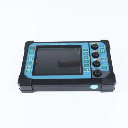
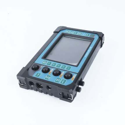
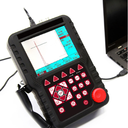
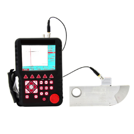
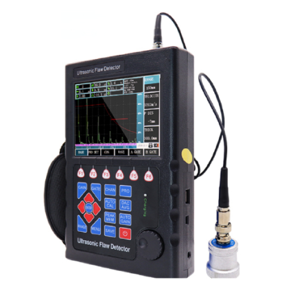
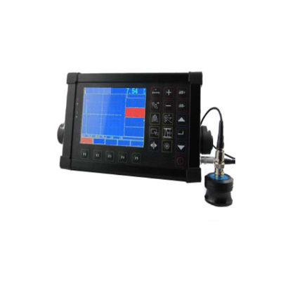
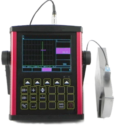
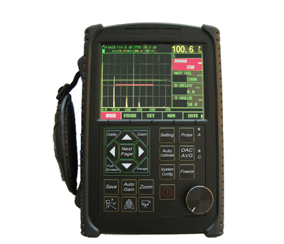
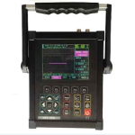
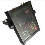
GAOTek Flaw Detector with 100 Independent Setup (3 Staff Gauge) is a portable industrial non-destructive flaw detector, which can rapidly inspect, evaluate and diagnose various defects (crack, inclusion and pinhole, etc.) in a work piece without destruction. This instrument can be widely used in any fields that need defect inspection and quality controlling e.g. manufacturing industry, metallurgical industry, metal working, chemical industry, etc., also be broadly used in the active safety inspection and service-life evaluation in such fields as aerospace, railway transportation and boiler pressure vessels, etc. It is an essential instrument for non-destructive inspection industry.
When the ultrasonic wave propagates in a job, one can detect the defect in it by the influence on the propagation of ultrasonic wave based on the acoustic characteristic demonstrated by the defect in the material. Based on this principle, by using ultrasonic wave one can measure such defects as crack, pinhole and inclusion in such media as metal, non-metal and composite, etc.
Key Features
- Automated calibration of transducer zero offset and/or velocity
- Automated gain, Peak Hold and Peak Memory
- Automated calculation of the size of flaw with wide bottom type in AVG function
- Automated display with precise flaw location
- Automated switch with three staff gauge
- High contrast viewing of the waveform from bright, direct sunlight to complete darkness and easy to read from all angles
- Large memory size of 500 A graph
- USB port present and easy communication with PC
- High-speed capture with very little noise
- Solid metal housing (IP65) and 6 dB DAC functions
- Li battery with continuous working time up to 10 hours
- Easy lock and unlock function of system parameters and electronic clock calendar
- Powerful pc software and reports can be exported to excel
Technical Specifications
Range of scanning | 0 – 236.22 in (6000 mm) |
D-delay | -20 ms – +3400 ms |
P-delay | 0.0 – 99.99 ms |
MTLVEL | 1000 m/s – 15000 m/s |
Frequency Range | 0.5 MHz – 10 MHz |
Gain adjustment | 0 – 110 dB |
Reject | 0 % – 80 % of screen height, step: 1 % |
Vertical linear error | Vertical linear error is not more than 3 % |
Horizontal linear error | Not more than 0.2 % in the scanning range |
Sensitivity Leavings | ≥62 dB |
Dynamic range | ≥34 dB |
Alarm | Three modes, i.e. forbidden wave, loss wave and auto |
A-Scan display area | Full screen or local, A-Scan display freezing and de-freezing A-Scan filling |
Data save | 500 A-Scan images (including setting of instrument) |
Battery | Li battery 7.4 V 4800 mAh |
Power adaptor | Input 100 V – 240 V/ 50 Hz – 60 Hz
Output 9 V DC/1.5 A |
Working temperature | -4 °F to -58° F (-20 °C – 50 ℃) |
Working humidity | 20 % – 90 % |
Overall dimension (mm) | 9.45 in x 7.09 in x 1.97 in (240 mm ×180 mm ×50 mm) |
Weight | 3.97 lbs (1.8 kg) |
Additional Information
Basic steps
- Insert the probe plug into the probe socket of the host, rotate the locking nut tightly
- Press
to turn on the instrument
- It will carry out self-test
- In normal case, when you turn on the unit, it will automatically enter into the status that it is in during last turning off. The instrument parameters are consistent with last turning off, but the waveform during last turning off will not display.
- Check voltage of the battery. If the power monitor shows that the voltage is low, it will turn off automatically 1 min after alarming bell.
- According to your application, ten independence setups can be applied, any criterion can be freely input and work can be carried out in the scene without test block.
- Measure and save results and Turn off the instrument
Starting the Instrument
Press to turn on the instrument. It will carry out self-test. After five seconds, the instrument will come into operation mode.
Note: Press “Combined Key” as start-up and loading of the program to execute some special functions.
Description about Screen Display
Three Screen Display Modes
- A-scan at Normal mode
- A-scan at Enlarged mode
You can activate Enlarged mode by . The gain and selected dB step value will be always displayed on the screen. And at the same time, all other functions are locked.
- Manual B-scanning
Fig. 3.7 B-scan mode
Description about Symbols Displayed on Screen
Echo amplitude H=84 %, depth to the reflector= 0.062 in (1.57 mm), surface distance= 0.990 in (25.14 mm), echo times is 2, start of range= 0.0 in, end of range= 1.575 in (40.0 mm)
Echo amplitude (pixels) H= 148, Angular distance= 1.099 in (27.68 mm).
Description about other symbols
Symbol | Name | Description |
![]() |
Freeze | Freeze state |
![]() |
Communication | The instrument is communicating with PC. |
![]() |
Angular distance | Distance from the incidence point to the reflected point. |
![]() |
Depth to reflector | Depth from the incidence point to the reflected point. |
![]() |
Surface distance | Surface distance from the incidence point to the reflected point. |
![]() |
Echo amplitude | The amplitude value of max echo within the gate. |
![]() |
Edge sampling |
It show that the instrument is in “Edge sampling” mode, depth and angular distance is the measure value of the first echo which is above the gate and within the gate. |
![]() |
Peak sampling | It show that the instrument is in “Peak sampling” mode,depth and angular distance is the measure value of the echo with the max amplitude within the gate |
P | Memory peaks | Peak memory function is enabled |
T | Making video | Dynamic Record function is enabled. |
E | Operation error | Operation error last time. |
![]() |
Radian revise | Abscissa and measure result is revised according to radian. |
Overview of All Functions
No. | Group | Functions | Description |
1 | BASE | RANGE, MTLVEL, D-DELAY , T-VALUE | Basic adjustment items necessary for the display range |
1 | PROBE | PROBE TYPE/ PROBE POS, ANGLE/K-VALUE, P-DELAY/ X-VALUE, X-COORD/ PART DIA | Probe adjustment items needed |
1 | SET | SETTING NO., RECALL/REFACTORY /SAVE/DELETE/CLEAR ALL | Relative items for independence setups |
1 | MEM | DATA NO, RECALL, SAVE, DELETE | Setting of data memory |
1 | GATE | GATE LOGIC/ALARM, aSTART/bSTART, aWIDTH/bWIDTH, aTHRESH/bTHRESH | Relative items for gate configuration |
2 | AUTO C | CSBT, CABT,aSTART/ aWIDTH, TYPE | Automated calibration of transducer |
2 | DAC1 | DAC/REVISE, RECORD/REVISE POS, aSTART/aWIDTH, SHOW MARK/DAC MODE | Plotting DAC curve |
2 | DAC2 | DAC-EL/ERS-REF, DAC-SL, DAC-RL, T-KORR/JDAC | Setting relative with DAC curve |
2 | AVG1 | AVG MODE/CHOCK VEL, PROBE NAME, FREQUENCY/DIAMETER, REF TYPE/REF SIZE | |
2 | AVG2 | A START/AVG CURVE, RECORD REF, TEST ATTN/CORRECT | |
3 | Pulse | ENERGY,Pulse width | |
3 | Gain | REF GAIN, ADD REF, SCAN DB, AUTO-80 | Relative items for gain |
3 | B / V | B-SCAN /A-SCAN, SCAN WAY/SCAN MODE, REVIEW/VIDEO | |
3 | CFG1 | DETECT/ REJECT, GRID/BRIGHTNESS, UNIT / BUZZER, DATE/TIME | |
3 | CFG2 | LANGUAGE, COLOR SET, ABOUT | |
4 | AWS | INDICA/ A START, REFRANCE, ATTEN, RATING |
Other special functions can be realized by Special Function (SF) keys. The functions of each SF keys are introduced in the following table.
Special Functions | Description of function |
Gain step | To adjust the gain step |
dB+ dB- | To adjust the gain |
Full-screen | To switch over in full screen |
Freeze | To freeze waveform |
Dynamic record | On/off Dynamic record |
Memory Peaks | Capture the max value of echo on the screen |
Measure display | Select the display mode of measure result on the screen |
Enter | Switch of multi-menu, parameters, confirmation of functions |
Page up | Switch function page |
Basic Operation Way
You can select a functional group by <Fn> key; select certain function by <Menu> key and . At this time, you can modify parameters of this current menu by +/- key and for some functional menus, they are shared by two functions, when you have selected such a function, by pressing
or the corresponding <Menu> key, it can be shifted to another function.
Selection of Functions
There are 5 functional groups displayed below the A-scan zone, which can be selected by the corresponding <Fn> key, and the selected one will be highlighted. The four corresponding function items will be displayed closely next to the right of A-scan zone, which can be selected by pressing “↑” or “↓” key.
Rough and Fine Adjustment of Functions
For some functions, rough and fine adjustments are available. By pressing down the corresponding key, you can shift between these two adjusting modes. With a symbol “*” in front of the function item that means it is in fine adjustment mode.
The following are the functional items with optional rough and fine adjustment.
Functions | Functional group |
RANGE | BASE |
MTLVEL | BASE |
D-DELAY | BASE |
T-VALUE | BASE |
Description of functions and operation way
Adjustment of BASE Group
In the BASE functional group, users can adjust and set the functional items relative with the display range, including RANGE, MTLVEL, D-DELAY and T-VALUE.
During the detection, the display range of screen is in great relation to the material of work piece and probe’s nature. The work piece material will influence the transmission velocity of ultrasonic wave.
Detection Range (RANGE)
It is to set the measuring range for screen display during detection
If what selected currently is RANGE functional menu, then by pressing , it is allowed to shift between Rough and Fine adjustment.
Operation:
- By <Page up> key, switch the function page.
- Select BASE functional group by <F1> key, and by “↑” or “↓” key, select the functional menu for RANGE, and then adjust parameters for RANGE by “+” or “﹣ ”
- Users can shift the Rough and Fine adjusting mode by key
.
Material velocity (MTLVEL)
Users are allowed to set the transmission velocity of ultrasonic wave in work piece.
If what selected currently is MTLVEL function menu, then by the key , it is allowed to shift between Rough and Fine adjustment.
Operation:
- By <Page up> key, switch the function page.
- Select BASE functional group By <F1> key, and by “↑” or “↓” key, select the functional menu for MTLVEL, and then adjust parameters for MTLVEL by “+” or “﹣ ”
- Users can shift the Rough and Fine adjusting mode by Enter key
.
Display starting point (D-DELAY)
Users can set the pulse shift during detection, viz. D delay. By which, users are allowed to adjust the starting position for waveform, as well as adjusting the zero point of pulse, so as to make sure that it is at the surface or a starting face inside the work piece. If the pulse has to be started from the surface of work piece, D delay must be set to 0.
Operation:
- By <Page up> key, switch the function page.
- Select BASE functional group by <F1> key, and by “↑” or “↓” key, select the functional menu for D-DELAY, and then adjust parameters for D-DELAY by “+” or “﹣ ”
- Users can shift the Rough and Fine adjusting mode by key
.
Thickness of work piece (T-VALUE)
It is to set the thickness of work piece during detection.
Rough and Fine adjustment can be switched by the key .
Operation:
- By <Page up> key switch the function page.
- By <F1> key select BASE functional group, and by “↑” or “↓” key, select the functional menu for T-VALUE, and then adjust the job’s thickness by “+” or “﹣ ”
- Users can shift the Rough and Fine adjusting mode by Enter key
.
Adjustment of PROBE Group
With this functional group, it is allowed to adjust and set the functional items in relation to ultrasonic sending and receiving, including PROBE TYPE/ PROBE POS, ANGLE/K-VALUE, P-DELAY/ X-VALUE, X-COORD/ PART DIA
P-DELAY/ X-VALUE
This menu is multipurpose for setting p-delay and x-value. By key , shift between P-DELAY and X-VALUE.
P-DELAY:
User can set the zero point of probe during detection, viz. P Delay. It is necessary to compensate the delay in probe resulted from acoustic beam in the pitch interval from energy exchanger to work piece by P Delay.
Operation:
- By <Page up> key, switch the function page.
- Select PROBE functional group By <F2> key, and by “↑” or “↓” key, select the functional menu for P-DELAY, and then adjust parameters for P-DELAY by “+” or “﹣”
X-VALUE:
It is to set the front edge of probe.
Operation:
- By <Page up> key switch the function page.
- By <F2> key, select PROBE functional group, and by “↑” or “↓” key, select the functional menu for X-VALUE, and then adjust the probe front edge by “+” or “﹣ ”
X-COORD/ PART DIA
This menu is multipurpose for setting X-COORD and PART DIA. By key , shift between X-COORD/ PART DIA.
X-COORD:
Coordinate mode means the definition of the horizontal coordinate line, including “S-PATH” “P-VAL” and “DEPTH”, when the refraction angle is not zero, the function above is effective, when it is zero the coordinate is defined as S-PATH.
Options: S-PATH, P-VAL, DEPTH
Operation:
- By <Page up> key switch the function page.
- By <F2> key select PROBE functional group, and by “↑” or “↓” key, select the functional menu for X-COORD, and then adjust the coordinate mode by “+” or “﹣ ”
PART DIA:
When we detect a pipe, we must input the outside diameter of part and thickness exactly. Part diameter is the outside diameter of pipe.
Operation:
- By <Page up> key switch the function page.
- By <F2> key select PROBE functional group, and by “↑” or “↓” key, select the functional menu for PART DIA, and then adjust diameter value by “+” or “﹣ ”
Adjustment of setting
Setting Group is used for Operations of detection setting. It includes SETTING, RECALL/REFACTORY, SAVE, DELETE/CLEAR ALL
Detection Setting (SETTING)
During the detecting in scene, users usually need to do the detection on several kinds of work piece or change the probe, thus they need to calibrate the instrument time after time. To solve this problem, 100 detecting settings are available in this device. Users can set 100 different settings and save them, switch among the settings when it needed.
Operation procedure:
- By <Page up> key switch the function page.
- By <F3> key select SET functional group, and by “↑” or “↓” key, select the functional menu for SETTING, and then adjust parameters for SETTING by “+” or “﹣”
Recall of settings (RECALL)/REFACTORY
This menu is multipurpose for gate logic and gate alarm. Users can shift the functions for RECALL and REFACTORY by Enter key .
RECALL:
Recalling the setting in detection setting, when it is completed successfully, the current detection parameter setting will be replaced by the recalled one.
Operation:
- By <Page up> key switch the function page.
- By <F3> key select SET functional group, and by “↑” or “↓” key, select the functional menu for RECALL, and then carry out calling by “+” or “﹣ ”
- If current setting has no setting, by left and right key, this functional menu will always display OFF; if it has any setting, by “+” or “﹣ ” key, it will show “Yes/No”, if you press key then you will call out setting, and by pressing any other key, you will cancel the calling.
REFACTORY:
Users can recover the ex-factory parameter setting when turning on the machine if necessary.
Saving settings (SAVE)/ Modify settings (Modify)
This menu is multipurpose for Modify and SAVE. Users can shift the functions for Modify and SAVE by the <Enter> key.
SAVE:
This functional menu is for saving setting.
Operation procedure:
Select Setting functional group By < F3> key, and by up/down key, select the functional menu for SAVE, and save the setting by “+” or “﹣ ” key.
Note:
- A symbol “*” appears before the setting number means that this setting has been set.
The new setting will replace the old one in the setting which has been set before.
- The new setting saved will not include DAC parameter setting which is auto-saved in the current setting.
- If the current setting is locked, the saving of setting will not work.
Modify:
Modify the setting in detection setting, when it is completed successfully, the current setting will be modify by the current detection parameters.
Operation:
Select Setting functional group By < Setting > key, and by up/down key, select the functional menu for Modify, and then recall the setting by “+” or “﹣ ” key.
Delete settings (DELETE)/CLEAR ALL
This functional menu is for delete setting.
DELETE:
Operation:
- By <Page up> key switch the function page.
- By <F3> key select SET functional group, and by “↑” or “↓” key, select the functional menu for DELETE, and then carry out calling by “+” or “﹣ ”
- If current setting has no setting, by left and right key, this functional menu will always display OFF; if it has any setting, by “+” or “﹣ ” key , it will show “Yes/No”, if you press key then you will delete setting.
CLEAR ALL:
- By <Page up> key switch the function page.
- By <F3> key select SET functional group, and by “↑” or “↓” key, select the functional menu for CLEAR ALL and then carry out calling by “+” or “﹣ ”
- If all setting has no setting, by left and right key, this functional menu will always display OFF; if it has any setting, by “+” or “﹣ ” key, it will show “Yes/No”, if you press key then you will clear all settings, and by pressing any other key, you will cancel the clear.
Adjustment of MEM Group
This is for adjusting the memorizing modes, calling out, deleting and saving the configured data and detection parameters. It includes such functional menus as DATA NO, RECALL, SAVE and DELETE.
This instrument has a memory capacity for 500 sets of data and detection parameters as well as DAC curves from A-scan.
Function group MEM (DATA NO.)
It is for setting the MEM group No. after selecting the functional menu for Group No.
Operation:
- By <Page up> key switch the function page.
- By <F4> key select MEM functional group, and by “↑” or “↓” key, select the functional menu for DATA NO, and then set group no. by “+” or “﹣ ”
Recalling a stored data set (RECALL)
It is to recall data under Waveform Save mode, and call out the data corresponding to current group no. When the recalling succeeds, the current waveform and detection parameters will be substituted by the saved waveform and detection parameters, and the waveform is frozen.
Operation procedure:
- By <Page up> key switch the function page.
- By <F4> key select MEM functional group, and by “↑” or “↓” key, select the functional menu for RECALL, and then carry out calling by “+” or “﹣ ” key.
- If current group no. has no data in it, by key Coder, this functional menu will always display OFF; if there is data existing in the group, by “+” or “﹣ ” key, it will show “Yes/No”, and now press the corresponding menu key or
, the data will be recalled, and press any other key to cancel recalling.
Storing a data set (SAVE)
This functional menu is for saving data. It is to save the current waveform data into the current group no. depending on the displayed save mode. Operation:
- By <Page up> key switch the function page.
- By <F4> key select MEM functional group, and by “↑” or “↓” key, select the functional menu for SAVE, and then carry out saving by “+” or “﹣” key.
Deleting a data set (DELETE) /CLEAR ALL
It is to delete data. This is to delete the data corresponding to current group No. When the deletion succeeds, “*” before this group no. disappears.
Operation:
- By <Next Page > key switch the function page.
- By F4 key select MEM functional group, and by Up/Down key, select the functional menu for DELETE.
- If current group no. has no data in it, by the rotary knob, this functional menu will always display OFF; if there is data existing in the group, by “+” or “﹣ ” key, it will show “Yes/No”, and now press the <Enter> key, the data will be delete, and press any other key to cancel delete.
CLEAR ALL:
- By <Next Page > key switch the function page.
- By F4 select MEM functional group, and by Up/Down key, select the functional menu for DELETE.
- By “+” or “﹣ ” key, the menu will show “Yes/No”, if you press the <Enter> key then you will delete all data. And by pressing any other key, you will cancel the clear.
Adjustment of GATE Group
It is used for adjustment of gate settings, including Gate logic, Gate alarm, Gate start, Gate width and Gate height.
Functions of gate during detection:
- To monitor whether the job has flaws in the set logic and range, if yes, it will alarm.
- To measure the position and size of flaw echo.
- This device is equipped with double-gate function: Gate A and Gate B, normally Gate A is used alone for detecting the work piece flaw, and the double-gate is usually used in the measuring and calibration of multi-echo, eg. Measuring the distance between surface echo and first echo during thickness measurement.
GATE LOGIC/ ALARM
This menu is multipurpose for gate logic and gate alarm. Users can shift the functions for GATE LOGIC and ALARM by Enter key .
GATE LOGIC:
Gate logic has four options: NONE, POS, NEG, MUL.
NONE: Gate monitoring is off
POS: When the echo amplitude is higher than the pre-set threshold of the gate, it will alarm
NEG: When the echo amplitude is lower than the pre-set threshold of the gate, it will alarm
MUL: State of double gates
Operation:
- By <Page up> key switch the function page.
- By <F5> key select GATE functional group, and by “↑” or “↓” key, select the functional menu for GATE LOGIC, and then adjust the gate logic by “+” or “﹣ ” key.
ALARM:
Setting of gate alarm:
It can be used for alarm of forbidden wave and loss wave depending on the setting of Gate Logic. That is, if the gate is at positive logic, when the echo amplitude is higher than the threshold, the buzzer alarms; if the gate is at negative logic, when the echo amplitude is lower than the threshold, the buzzer alarms. When the DAC is opened, the DAC-REF is instead of gate to determine alarms.
Options:
ON:the buzzer is on
OFF: the buzzer is off
Operation procedure:
- By <Page up> key switch the function page.
- By <F5> key select GATE functional group, and by “↑” or “↓” key, select the functional menu for ALARM, and then turn on/off the buzzer by “←” or “→” key.
Starting point of the gates (aSTART/bSTART)
This functional menu is multipurpose for Start of Gate A and Gate B. Users can shift the functions for aSTART and bSTART by key .
aSTART:
Operation procedure:
- By <Page up> key switch the function page.
- By <F5> key select GATE functional group, and by “↑” or “↓” key, select the functional menu for aSTART, and then adjust the starting position of Gate A by “+” or “﹣ ” key.
bSTART:
Operation procedure:
- By <Page up> key switch the function page.
- By <F5> key select GATE functional group, and by “↑” or “↓” key, select the functional menu for bSTART, and then adjust the starting position of Gate B by “+” or “﹣” key.
Width of the gates (aWIDTH/bWIDTH)
This functional menu is multipurpose for Width of Gate A and Gate B, when this menu is selected, by you can shift the two functions.
aWIDTH:
Operation procedure:
- By <Page up> key switch the function page.
- By <F5> key select GATE functional group, and by “↑” or “↓” key, select the functional menu for aWIDTH, and then adjust the width of Gate A by “+” or “﹣ ” key.
bWIDTH:
Operation procedure:
- By <Page up> key switch the function page.
- By <F5> key select GATE functional group, and by “↑” or “↓” key, select the functional menu for bWIDTH, and then adjust the width of Gate B by “+” or “﹣ ” key.
Response and measurement threshold (aTHRESH/bTHRESH)
This functional menu is multipurpose for Threshold of Gate A and Gate B, when this menu is selected , by you can shift the two functions.
aTHRESH:
It is to set the threshold of Gate A. The parameter is expressed in percentage, i.e. the percentage in relative to the full amplitude.
Operation procedure:
- By <Page up> key switch the function page.
- By <F5> key select GATE functional group, and by “↑” or “↓” key, select the functional menu for aTHRESH, and then adjust the threshold of Gate A by “+” or “﹣ ” key.
bTHRESH:
It is to set the threshold of Gate B. The parameter is expressed in percentage, i.e. the percentage in relative to the full amplitude.
Operation procedure:
- By <Page up> key switch the function page.
- By <F5> key you select GATE functional group, and by “↑” or “↓” key, you select the functional menu for bTHRESH, and then adjust the threshold of Gate B by “+” or “﹣ ” key .