Description
Key Features
- Compliant with SFF-8472
- Up to 1.25Gb/s data links
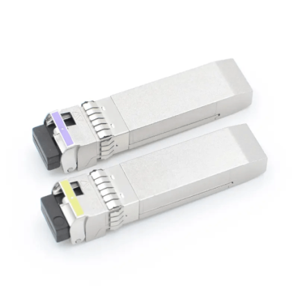
- FP laser transmitter for GAO-GBICBD-106
- DFB laser transmitter for GAO-GBICBD-106
- Up to 6.2 Miles(10Km) on 9/125µm SMF
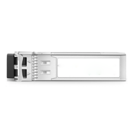
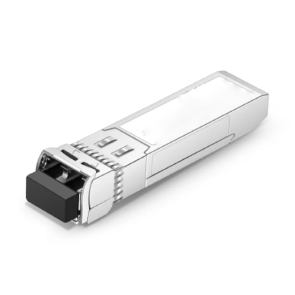
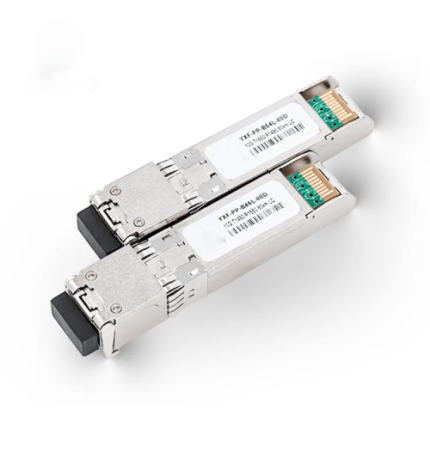
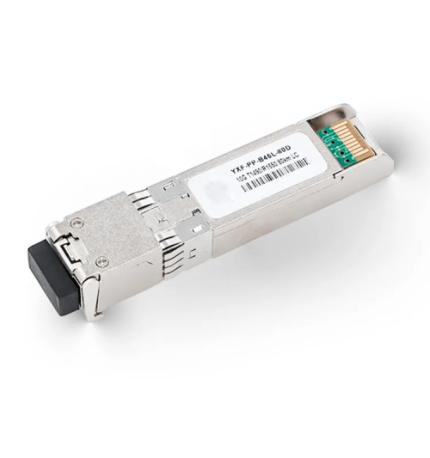
- GBIC footprint
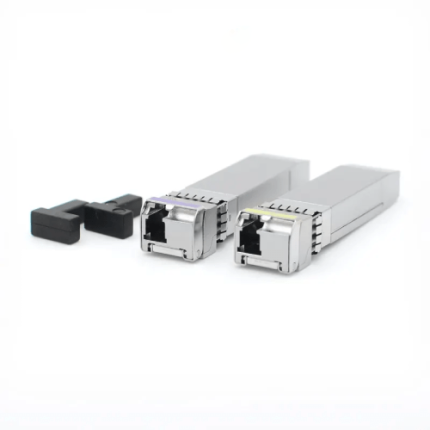
- BIDI SC/UPC type pluggable optical interface
- Low power dissipation
- Metal enclosure, for lower EMI
- RoHS compliant and lead-free
- Single +5V power supply
- Case Operation Temperature range from 32°F to +158°F(0°C to +70°C)
Technical Specifications
| Standard | SFF-8472 |
| Working Range | Up to 6.2 Miles(10 Km) |
| Data rate | 1.25Gb/s |
| Wavelength | 1310~1490nm |
| Transmitter Off Output S Power | -45dBm |
| Receiver Sensitivity | -20dBm |
| Receiver Input Saturation Power(Overload) | -3dBM |
| Supply Voltage | 0-6V |
| Transmitter Differential Line Input Impedance | 90-110Ω |
| Dimensions | 2.2in*1.08in*0.46 in (L 57.1mm*W 27.6mm*H 11.9mm) |
| Relative Humidity | 5% to 95% |
| Storage Temperature | -40°F to 185°F (-40°C to 85°C) |
| Case Operating Temperature | 32°F to +158°F (0°C to 70°C) |
PIN Descriptions:
| Pin | Symbol | I/O Type | Functional Description |
| 1. | RX_LOS | Output | Receiver Loss of Signal, Logic high, Open collector compatible 4.7K to 10K Ohm pulls up to VDDT on host. |
| 2. | RGND | Receiver Ground | |
| 3. | RGND | Receiver Ground | |
| 4. | MOD_DEF(0) | Output | Module Definition 0 TTL Low |
| 5. | MOD_DEF(1) | Input | Module Definition 1 Two wire serial ID interface SCL, 4.7K to 10K Ohm pull up to VDDT on host |
| 6. | MOD_DEF(2) | I/O | Module Definition 2 Two wire serial ID interface SDA, 4.7K to 10K Ohm pull up to VDDT on host |
| 7. | TX_DISABLE | Input | Transmitter Disable – Module disable on high or open (No Used) |
| 8. | TGND | Transmitter Ground | |
| 9. | TGND | Transmitter Ground | |
| 10. | TX_FAULT | Output | Transmitter Fault Indication, Logic high, open collector Compatible , 4.7K to 10K Ohm pull up to VDDT on host |
| 11. | RGND | Receiver Ground | |
| 12. | -RX_DAT | Output | Inverse Received Data Out, Differential PECL, at AC couple |
| 13. | +RX_DAT | Output | Received Data Out, Differential PECL, at AC couple |
| 14. | RGND | Receiver Ground | |
| 15. | VDDR | Input | Receiver Power |
| 16. | VDDT | Input | Transmitter Power |
| 17. | TGND | Transmitter Ground | |
| 18. | +TX_DAT | Input | Transmitter Data In, Differential PECL, AC couple |
| 19. | -TX_DAT | Input | Inverse Transmitter Data In, Differential PECL, AC couple |
| 20. | TGND | Transmitter Ground |
Electrical Interface Characteristics
| Parameter | Symbol | Min | Typ. | Max | Unit | Note |
| Transmitter | ||||||
| Total Supply Current | ICC | A | mA | Note(1) | ||
| Transmitter Disable Input-High | VDISH | 2 | Vcc+0.3 | V | ||
| Transmitter Disable Input-Low | VDISL | 0 | 0.8 | V | ||
| Transmitter Fault Input-High | VDISL | 2 | Vcc+0.3 | V | ||
| Transmitter Fault Input-Low | VTxFH | 0 | 0.8 | V | ||
| Receiver | ||||||
| Total Supply Current | Icc | B | mA | Note(1) | ||
| LOSS Output Voltage-High | VLOSH | 2 | Vcc+0.3 | V | LVTTL | |
| LOSS Output Voltage-Low | VLOSL | 0 | 0.8 | V | ||
Note (1): A (TX) + B (RX) = 300mA (Not include termination circuit)

Applications:
- Switch to Switch Interface
- Gigabit Ethernet
- Switched Backplane Applications
- Router/Server Interface
- Other Optical Links