Description
Key Features
- Complies with IEEE802. 3ah 1000Base-PX20 application
- Bi-directional 1.25Gbps Upstream/1.25Gbps Downstream
- 4 Miles (20Km) transmission distance
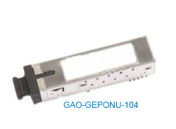
- SFP package with SC Receptacle
- 1490nm continuous-mode 1.25Gb/s DFB transmitter
- 1310nm burst-mode 1.25Gb/s APD receiver
- LVTTL Bias Control input and Rx Signal Detect output
- Laser Class 1 Product which complies with the Requirements of IEC 60825-1 and IEC 60825-2
- Single +3.3V power supply
Technical Specifications
| Protocol | 2-wire serial communication |
| Working Range | Up to 12.4miles (20km) |
| Standards | IEEE802.3ah Gigabit Ethernet
Laser Class 1 Product with the Requirements of IEC 60825-1 and IEC 60825-2 IEC/EN 61000-4-2 IEC/EN 60950 ROHS 2002/95/EC |
| Data rate | 1.25 Gb/s |
| Wavelength | 1310nm |
| Connector Type | SC/UPC Connector |
| Transmitter Extinction Ratio | 9dB |
| Transmitter OFF Output Power | -39dBM |
| Transmitter Differential Line Input Impedance | 80-120 Ω |
| Receiver Sensitivity | -30 dBm |
| Receiver Input Saturation Power | -8 dBm |
| Dimensions | 2.70 in x 0.52in x0.33in( 68.8×13.4×8.5 mm) |
| Supply Voltage | -0.3 to 4V |
| Storage Temperature | -40 °F to 185 °F (-40°C to 85°C) |
| Storage Ambient Humidity | 5% to 95% |
| Case Operating Temperature | 32°F to 158°F (0°C to 70°C) |
PIN Descriptions:


Notes:
- TX Fault is an open collector/drain output, which should be pulled up with a 4.7K – 10KΩ resistor on the host board. Pull up voltage between 2.0V and VccT, R+0.3V. When high, output indicates a laser fault of some kind. Low indicates normal operation. In the low state, the output will be pulled to < 0.8V.
- TX disable is an input that is used to shut down the transmitter optical output. It is pulled up within the module with a 4.7 – 10 K Ω resistor. It’s states are:
- Low (0 – 0.8V): Transmitter on
- (>0.8, < 2.0V): Undefined
- High (2.0 – 3.465V): Transmitter Disabled
- Open: Transmitter Disabled
- Mod-Def 0, 1, 2. These are the module definition pins. They should be pulled up with a 4.7K – 10KΩresistor on the host board. The pull-up voltage shall be VccT or VccR. Mod-Def 0 is grounded by the module to indicate that the module is present Mod-Def 1 is the clock line of two wire serial interface for serial ID Mod-Def 2 is the data line of two wire serial interface for serial ID
- LOS (Loss of Signal) is an open collector/drain output, which should be pulled up with a 4.7K – 10KΩ resistor. Pull up voltage between 2.0V and VccT, R+0.3V. When high, this output indicates the received optical power is below the worst-case receiver sensitivity (as defined by the standard in use). Low indicates normal operation. In the low state, the output will be pulled to < 0.8V.
- VeeR and VeeT may be internally connected within the SFP module.
- RD-/+: These are the differential receiver outputs. They are AC coupled 100Ω differential lines which should be terminated with 100Ω (differential) at the user SERDES. The AC coupling is done inside the module and is thus not required on the host board. The voltage swing on these lines will be between 370 and 2000 mV differential (185 – 1000 mV single ended) when properly terminated.
- VccR and VccT are the receiver and transmitter power supplies. They are defined as 3.3V ±5% at the SFP connector pin. Maximum supply current is 300mA. Recommended host board power supply filtering is shown below. Inductors with DC resistance of less than 1 ohm should be used in order to maintain the required voltage at the SFP input pin with 3.3V supply voltage. When the recommended supply-filtering network is used, hot plugging of the SFP transceiver module will result in an inrush current of no more than 30mA greater than the steady state value. VccR and VccT may be internally connected within the SFP transceiver module.
- TD-/+: These are the differential transmitter inputs. They are AC-coupled, differential lines with 100Ω differential termination inside the module. The AC coupling is done inside the module and is thus not required on the host board. The inputs will accept differential swings of 500 – 2400 mV (250 – 1200 mV single-ended), though it is recommended that values between 500 and 1200 mV differential (250 – 600 mV single-ended) be used for best EMI performance.
Electrical Interface Characteristics

Note (1): Internally AC Coupled, but requires a 100Ohm differential termination at or internal to Serializer/ Deserializer.
Note (2): When los output is high, RX out is no signal
Timing Characteristics for Digital RSSI


Burst Mode Digital Diagnostic Monitor Interface (DDMI) Description
The DDMI can detect TX power, RX power, Bias current, Temperature and VCC.
| Monitor Scope | Monitor Error | |
| TX power | -3dBm ~8 dBm | ±3dBm |
| RX power | -8dBm~30dBm | ±3dBm |
| Bias | 0mA~90mA | ±10% |
| Temperature | -40°F to 185°F | ±41°F |
| Vcc | 2.8V~3.8V | ±5% |
Recommended Interface Circuit

Regulatory Compliance

Outline Dimensions
| Parameter | Unit | Description | Note |
| Mechanical Dimensions | Inches(mm) | 2.7 x0.52 x0.33
(68.8×13.4×8.5) |
|
| Connector Type | – | SC/UPC Connector | IEC-61754-4 |

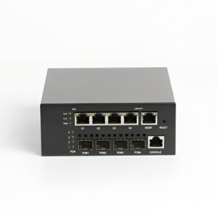
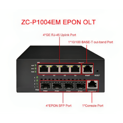
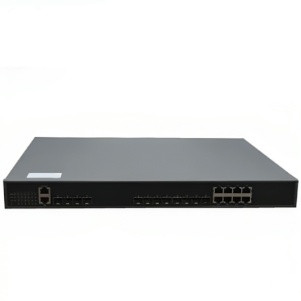
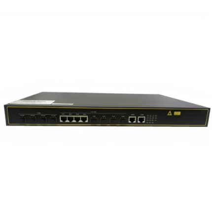
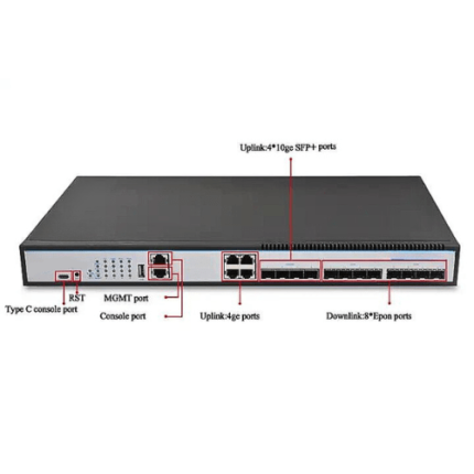
Applications:
- Gigabit Ethernet Passive Optical Network (GEPON) OLT