Description
Overview
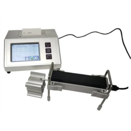
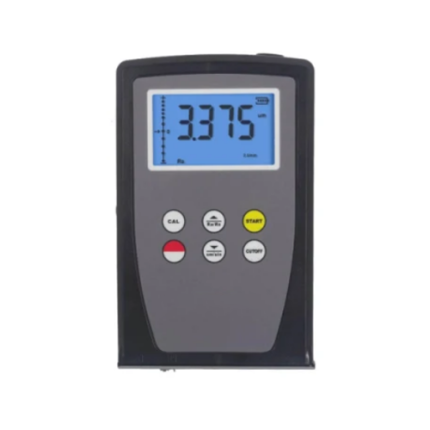
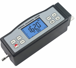
GAOTek High Speed Surface Roughness Tester (Data Storage) is designed by huge data storage that stores 100 item of raw data and waveforms and can be used to measure surface roughness of various machinery-processed parts in the production site. It provides huge capacity data storage that stores 100 item of raw data and waveforms. This tester is capable of evaluating surface textures with a variety of parameters according to various national standards and international standard. It can work continuously for more than 20 hours. The measurement results are displayed digital/graphically on the OLED, and output to the printer. This small handheld surface roughness tester is suitable for shop floor and mobile measurements.
Key Features
- DSP chip to control and data processing, high speed and low power consumption
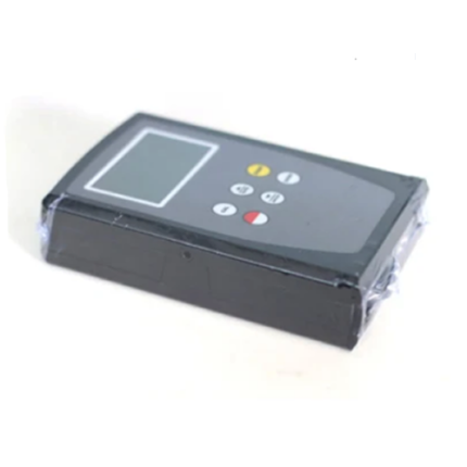
- Electromechanical integration design, small volume, light weight and easy to use
- Plastic shell, portable and high reliability.
- Testing parameters are Ra, Rz, Rq, Rt, Rp, Rv, R3z, R3y, RzJIS, Rsk, Rku, Rsm, Rmr, Rx, RPc, Rk, Rpk, Rvk, Mr1, and Mr2.
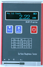
- 128 x 64 OLED dot matrix display, digital / graphic display
- Intuitive and rich display information, can display all the parameters and graphics
- Compatible with ISO, DIN, ANSI, JIS national standards
- Residual quantity icon, prompting the user to charge
- Continuous working time more than 20 hours
- Real-time clock settings and display, convenient data recording and storage
- Supports automatic dormancy, automatic shutdown and power saving function
- Reliable control motor to go dead circuit and software design
- Measurement information display, menu prompt information, false information and switch machine.
- Can be connected to a computer and printer
- Optional Bluetooth function.
Technical Specifications
| Sensor | |
| Principle | The displacement differential inductance |
| Stylus | Natural Diamond, 90° cone angle, 5 μm tip radius |
| Force | <4 mN |
| Skid | Ruby, Longitudinal radius 1.57 in (40 mm) |
| Measuring Range | |
| Ra | 0.005 μm to 16.000 μm |
| Rz | 0.02 μm to 160 μm |
| Maximum Drive Stroke | 0.7 in (17.5 mm) |
| Resolution Ratio | 0.01 μm / ±20 μm |
| 0.02 μm / ±40 μm | |
| 0.04 μm / ±80 μm | |
| Testing Parameter | Ra, Rz, Rq, Rt, Rp, Rv, R3z, R3y, RzJIS, Rsk, Rku,Rsm, Rmr, Rx, RPc, Rk, Rpk, Rvk, Mr1, Mr2 |
| Other Specifications | |
| Sampling Length | 0.009 in, 0.03 in, 0.09 in (0.25 mm, 0.8 mm, 2.5 mm) |
| Standard | ISO, ANSI, DIN, JIS |
| Evaluation Length | ( 1-5)L |
| Indication Accuracy | 0.001 |
| Indication Error | ±(7-10) % |
| Variability | <6 % |
| Data Storage | 100 groups |
| Battery Type | Lithium battery (rechargeable) |
| Dimension | 2.16 in × 2.5 in × 1.81 in
(158 mm × 63.5 mm × 46 mm) |
| Weight | 10.58 oz. (About 300 g) |
| Relative Humidity | < 90 % |
| Working Temperature | -4 °F ~ 104 °F (-20 °C ~ 40 °C) |
Additional Information
Measurement Principle
When measuring roughness of part surface, the pickup is placed on the surface of the part and the surface is traced at constant rate. The pickup acquires the surface roughness by the sharp stylus in pickup. The roughness causes displacement of pickup which results in change of inductive value of induction coils thus generating analogue signal which is in proportion to surface roughness at output end of phase-sensitive rectifier. This signal enters data collection system after amplification and level conversion. Those collected data are processed with digital filtering and parameter calculation by DSP chip and the measuring result can be read on OLED, printed through printer and communicated with PC.
Measuring Range
| Parameter | Measuring Range |
| Ra Rq | 0.005 μm~16 μm |
| Rz R3z Ry Rt Rp Rm | 0.02 μm~160 μm |
| Sk | 0~100% |
| S
Sm |
0.03 in (1 mm) |
| tp | 0~100% |
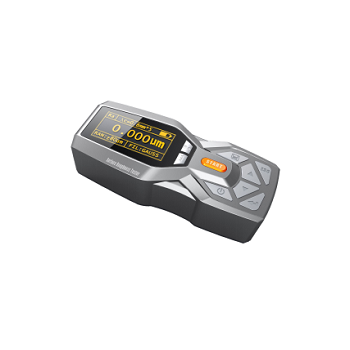
Name of Each Part


- sensor
- display
- key area
- adjustable support

- USB charge
- Power switch
- Fixing hole
Buttons Define

Battery Charging
When battery voltage is too low, the instrument should be charged as soon as possible. Use USB port of the instrument for charging. You can use the built-in power adapter for charging, you can also use computer’s USB port for charging. If you use the other power adapter for charging, the output voltage should be 5 V DC, the current should be greater than 800 mA.
Instrument displays charging animation when charging after full animation ends, the display is full of symbols. Charging time is of 2.5 hours.
This instrument adopts lithium ion chargeable battery without memory effect and charging can be fulfilled at any time without affecting normal operation of the instrument.
Connection Method of Sensor and Main Unit

Installation and Removing of sensor
For installation, hold the main body of sensor with hand, push it into connection adapter at the bottom of the instrument as shown in Figure and then slightly push it to the end of the sheath. To remove, hold the main body of pickup or the root of protective sheath with hand and slowly pull it out.
Measuring Operation
Preparation for Measurement
- Switch-on to check if battery voltage is normal;
- Clear the surface of part to be measured;
- Place the instrument correctly, stably and reliably on the surface to be measured;
- Trace of the pickup must be vertical to the direction of process line of the measured surface.


Turning On/Off
Press the key![]() to hold 2 seconds. After the instrument automatically boots, it will display equipment type, name and manufacturer information. Then enter the basic measurement status main display interface, as shown.
to hold 2 seconds. After the instrument automatically boots, it will display equipment type, name and manufacturer information. Then enter the basic measurement status main display interface, as shown.

Introductions:
- The last shutdown set content will be displayed in the next boot.
- Start-up and shutdown; press and hold the key for about 2 seconds to open the instrument will perform the appropriate action.
- Long-time not to use, the instrument should be on the side of the power switch turned off.
- Start measuring sensor is installed, please refer to the stylus position and try to adjust the stylus cursor position to the best position “0”.
Stylus Position
First, use the stylus position to determine the location of the sensor. The stylus as measured in the middle position.
In the main interface mode, press the stylus position ![]() key switches stylus position display screen and the main display screen.
key switches stylus position display screen and the main display screen.

Start measurement
In the main interface mode, press the Start button to start measuring

The results of all the measurements can be observed, as seen in the figure

Print measurement results
The instrument can be connected to the printer. The measurement results will be printed. After measurement, Press ![]() key to display the measurement results.Press
key to display the measurement results.Press ![]() key to print the measured data to a serial printer. At this point,
key to print the measured data to a serial printer. At this point, ![]() key is a print key to use.The instrument can be tested according to the actual requirements of arbitrary parameters choose to print or print all the parameters.
key is a print key to use.The instrument can be tested according to the actual requirements of arbitrary parameters choose to print or print all the parameters.

In the main display interface mode, press the![]() key to save the measurement results stored in the instrument memory. Instrument built-in large capacity memory, can store 100 groups of raw data and waveform data.
key to save the measurement results stored in the instrument memory. Instrument built-in large capacity memory, can store 100 groups of raw data and waveform data.
Data storage recording date and time the file name automatically generated according to the last data record is always stored the most recent recording time, the last data record stored recording record number will be 001.

In the basic measurement mode, press the![]() key to enter the menu operation state, press the
key to enter the menu operation state, press the![]() keys to select “Preferences” functionand then press the
keys to select “Preferences” functionand then press the ![]() key to enter the parameter setting mode. In the parameter setting mode, you can modify all the measurement conditions.
key to enter the parameter setting mode. In the parameter setting mode, you can modify all the measurement conditions.

In the basic measurement mode, press the ![]() key to enter the menu operation state, Press the
key to enter the menu operation state, Press the ![]() keys to select “Recoder” function, Press the
keys to select “Recoder” function, Press the![]() key to enter management projects.
key to enter management projects.

Recoder management by the two project components
- View 2. format.
Selected item and press the Enter key to enter.
View Record

Select the appropriate records, press ![]() View log content. In view records content,
View log content. In view records content, ![]() data can be printed according to the specified printer, operate the following figure.
data can be printed according to the specified printer, operate the following figure.

Format
Data format is the deletion of data records, once formatted and all data will be cleared. In the data before formatting instrument has confirmation prompt information, user data will not be restored after confirmation.

Date Settings
Built-in real time clock calendar instrument used to record information about the test of time to adjust date and time as follows

Software Information
Instruments software and hardware information can help users easily upgrade and maintain the product, unique serial number of the instrument software information items are displayed.

Parameter Calibration
Before measuring instrument, standard calibration block is required. The instrument is configured with a standard calibration block, before measurement. Under normal circumstances, when the measured value and the block value of the difference in the acceptable range, the measurement value is valid, can be measured directly.
If the measured value and the block value of the difference is greater than an accuracy error range of the instrument, or the user requires higher accuracy, can be used to correct the indication calibration function and improve measurement accuracy. Showing the value of the calibration procedure as shown.

- Under normal circumstances, the instrument in the factory have been rigorously tested, showing error is much less than ±10 %, in this case, the user is not showing the value of the calibration frequently used functions.
- After setting the calibration value, you must press the
 key for a full measurement, instrument calibration to be valid.
 - New parameters after calibration must be carried out once a complete measurement and press the key
 is stored in the instrument.
 - Press “ESC”key to return the menu without saving calibration results.
Print setup
The instrument can be tested according to the actual requirements of any parameter selection Print or Print All, the steps shown in Figure.

Options and Usage
Adjustable Support
When measured surface of part is smaller than the bottom surface of the instrument, sheath of pickup and adjustable supporter of instrument options can be used for auxiliary support to complete the measurement (as shown in Figure).

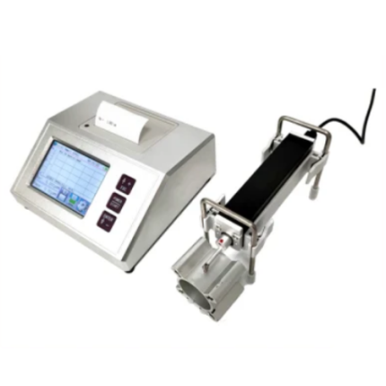
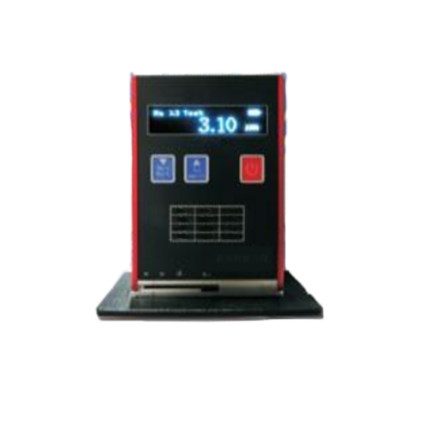
Measurement Stand
Measurement Stand can adjust the positions between tester and measured part conveniently with flexible and stable operation and wider application range. Roughness of complex shapes can also be measured. Measurement stand enables the adjustment of the position of stylus to be more precise and measurement to be more stable. If Ra value of measured surface is relatively low, using measurement platform is recommended.

Extending Rod
Extending rod increases the depth for pickup to enter the part. Length of extending rod is 1.96 in (50 mm).

Standard Sensor
The standard sensor can measure most of the plane, inclined plane, cone surface, inner hole, groove and other surface roughness. In addition to the standard sensor, other special sensors are needed to measure the measuring platform.


Curved Surface Sensor
Curved surface sensor is mainly used for measuring radius is larger than the smooth cylindrical 3mm surface roughness, for the larger radius smooth spherical surface and other surface also can obtain good approximation, the radius of curvature, the surface is smooth, the better the effect of measurement.

Pinhole Sensor
Using Pinhole pickup, the inner surfaces of holes with radius more than 0.07 in (2 mm) can be measured. Refer to the following Figure for detailed dimension.
Deep Groove Sensor
With deep groove sensor, it is possible to measure groove with width wider than 0.11 in (3 mm) and depth deeper than 0.39 in (10 mm), or the surface roughness of step with height less than 0.39 in (10 mm). Also can be used to measure the planar, cylindrical used with platform. Please see figure for detailed dimension.


General Maintenance
Sensor
- Swap sensors should be handled carefully. Do not touch the guide head and a stylus, because this is a key part of the whole instrument.
- To complete the measurement work, keep the sensor into the box.
- Please pay attention to protect the needle part measuring
- The sensor’s precision components, knock, touch, fall off phenomenon may damage the sensor. You should try to avoid such
Main Unit
- Pay attention to maintaining the Main Unit surface clean. Use a soft dry cloth to clean its surface.
- The instrument is a precision measuring instrument. It should always be handled with care, to avoid the
Battery
- Always observe the battery prompt, when the low voltage, please
- The charging time is 3 hours. Do not try to charge for a long time.
Standard Sample Plate
- The surface of a standard sample plate must be kept
- Avoid scratches on the surface of sample
Troubleshooting:
| Error Message | Cause | Solutions Method |
| Motor error | Motor stuck | Reboot |
| Out of Range | 1. The measured surface signal exceeding the measurement range
2. Placed away from the center of the stylus position |
Increase measuring Range
Adjust the Stylus Position |
| No test data | After the boot does not measure | The actual measurement: one time |
| Measurement Accuracy
Out of Range |
Set the parameter error
Calibration data error |
Set the parameter measurement
Calibrate the tester |