Description
Overview
The GAOTek Optical Power Meter with Insertion Loss is a portable tester which enables the user to measure power of optical output accurately. The stability and reliability can be enhanced effectively with this optical power meter with backlight switch. This power meter can perform insertion loss test of optical devices. It is widely used for installation, maintenance, debugging of fiber networks, optical fiber transmission, CATV, etc.
Key Features
- High end portable device
- Insertion loss test of optical device.
- Optional Auto-off function
- Measurement of the power of optical sender (dBm and W)
- Back light switch.
- User self-calibration function.
- Has FC/SC/ST general purpose interfaces.
- 9 V laminated battery with 200 hrs battery life.
- Easy to choose the desired wavelength value with the wavelength key
- Relative power measurements to determine power loss
- Auto shut-down when there is no operation within 15 mins
- Indicates when connecting the AC adapter to a screen
- Absolute power measurement; using one major bridle wire
Technical Specifications
| Wavelength | 800 nm ~1700 nm |
| Detect Limit | 0.03 in (1.00 mm) |
| Probe | In GaAs |
| Uncertainty Degree | ±0.5 dB |
| Power Detecting Range | -70 dBm ~+10 dBm |
| Display Resolution | 0.01 dBm |
| Standard Wavelengths | 850 nm, 1300 nm, 1310 nm, 1490 nm, 1550 nm, 1625 nm |
| Power Supply | 9V battery, AC Adapter |
| Auto Backlight off | 30 seconds without any operation |
| Auto Power off | 15 minutes without any operation |
| Battery Life | 200 hours |
| Working Temperature | -4°F ~+ 158 °F (-20 °C to 70 °C) |
| Storage Temperature | -22 °F ~+ 176 °F (-30 °C to 80 °C) |
| Dimensions (L x W x H) | 7.28 in x 4.13 in x 1.96 in
(185 mm x 105 mm x 50 mm) |
| Weight | 0.77 lbs. (350 g) |
Additional Information
- How to use:
Start-up and shut-down
- Press power button to turn the tester on.
- Press power button and hold for approximately 2 seconds to turn off.
Auto-Off Function
- The Auto-off function is automatically enabled when the device is turned on.
Backlight
- The backlight is on when any key is pressed and the tester is turned on.
Wavelength Key
- This key selects the desired wavelength value at certain ranges. Once confirmed, the value is displayed on the left upper corner of the screen.
Power Conversion Key
- This button can be used for the conversion between the absolute and relative measurements of optical power.
Calibration Key
- This button saves the current power value as reference value or switches to relative power measurement depending on how long you press the key
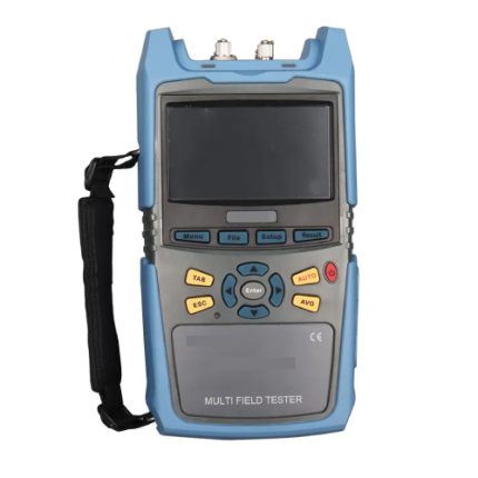
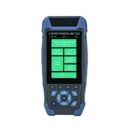
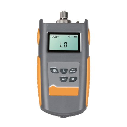
- The below figure shows the different keys of the device.

- Handling Instruction:
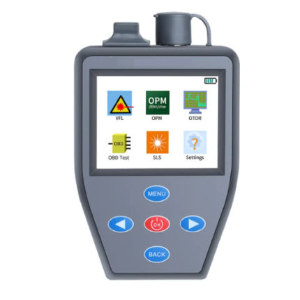
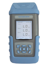
2.1 Information on LCD
After pressing the power key to start the meter, the following information will be shown on LCD as below,

(1) If the meter is supplied by battery, the icon at the left bottom will be ON. When the electric amount of battery is reduced, the display segment of battery becomes less automatically.
(2) When connected with AC adapter, an icon will be lightened at the middle of screen, at the same time, the electric amount icon will be in is ON mode.
(3) At the left lower position, an icon for Auto-off function is activated simultaneously and the icon is lightened as well, but if there is no operation, the meter will be shut down 15mins later.
(4) At the middle display-area of screen, the value of power will be displayed, the units are dBm, W, dB.
(5) The right upper display-area of screen shows reference power value, and the wavelength value at the left.
(6) The user self-calibration function is just the course of power conversion and calibration. (calibration of each wavelength)
- After opening the battery cover. Turn the toggle switch to “ON” position, then it can carry out the power calibration after start-up.
- The details of calibration are shown as follows:
| REF Key | Every time when we press it, a 0.05 dB value gets increased from the current value and the value is showed on the LCD screen. |
| dBm/W Key | Every time when we press it, a 0.05 dB value gets deducted from the current value and the value is showed on the LCD screen. |
| Wavelength Key | Used for the selection of wavelength |
| ON/ OFF Key | To save the value calibrated, press this key shortly.
Press this key for 2 secs to of the power meter |
- Open the battery cover, turn the toggle switch to OFF position for normal operation.
ATTENTION: It is strongly suggested that the fiber power meter should be measured or calibrated so that the accuracy and reliability can be guaranteed.
2.2 Wavelength Selection
There is a wide range of wavelength including 850 nm, 1300 nm, 1310 nm, 1490 nm, 1550 nm and 1625 nm for your option, it is available to carry out switch through the press of power key
2.3 Absolute Power Measurement
(1). Use one major bridle wire to connect the output port of light source and the detecting port of fiber power meter as shown in the following fig:

(2) Turn on the light source to enter working mode and select wavelength to be tested.
(3) Turn on the fiber power meter and select specified wavelength. (Selection method: press the key to select the desire wavelength value)
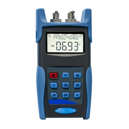
(4) The current power value on screen is just the absolute power value of current output of light source as shown in the following Fig (the current value is -09.73 dBm):

2.4 Relative Power (LOSS)
Measurement Relative power measurements are used to determine the power loss between two points in the system. The power level is first measured at one point and that value is saved in the meter as a reference. The power is then measured at another point. The meter subtracts the reference value from the new reading and displays the difference in dB
(1)Connect the desired connector to the meter, connect the two ends of optical fiber jumper with light source and power meter.

(2) Turn on the light source and power meter to enter working mode and select wavelength to be tested.
(3) When the output power of light source has been detected, just press ‘ref’ key, this power value will be stored as the current reference valve (this power value consists of actual output power of light source and loss value caused by major test bridle wire)

(4). Connect the tested optical fiber jumper with light source and power meter.

(5). Shortly press ‘ref’ key, the value on screen is the loss value of the bridle wire being inserted.

(6) To measure the loss of optical fiber link, it is necessary to carry out local initialization reference for light source and optical power meter, as shown in the following picture below. Read the initial reference value on optical fiber meter, and press the ‘ref’ key continuously to save this reference value.

(7) Put the light source and this optical fiber meter at the two ends of optical fiber link being tested respectively, the value on power meter is just the loss value of optical fiber link being tested (including the loss of linker).

3.Maintenance
- Always clean the optical connector each time a connector is attached.
- Avoid exposing the unit to extreme temperature. Condensation can form inside the unit and affect proper operation.
- Ensure the dust cap is in place any time a connector is not attached.
- Store the unit in clean and dry place.
3.1 Probe Cleaning
Clean the probe of optical power meter regularly.
- Open the dust-proof cap
- Screw off the adapter of power meter
- Use 0.09 in (2.5 mm) special cotton swab with some anhydrous alcohol to clean the surface of probe slightly.
WARNING: When clean the probe of optical power meter, it is forbidden to use any hard thing to touch the surface of probe in case cause damage to probe; in addition, keep away from a strong force to avoid crack of probe. Otherwise, the accuracy of measurement value will be reduced, even it fails to carry out any measurement.
ATTENTION: When the optical power meter is under idle mode, cover the dust-cap to keep the optical power meter clean.
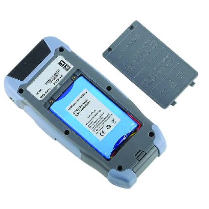
3.2 9 V battery replacement
- When install or take out the battery, the following information may be helpful for your operation:
- When the battery energy is lower or no 9 V battery installed, an icon will be displayed on screen.
- Only an eligible 9 V battery can be engaged
- If no use for a long time, take out the 9V battery in case of corrosion and damage to internal components.
3.3 Calibration and measurement
Under proper conditions, if this meter can be used in a right way, a better performance can be guaranteed. In order-to guarantee the performance, it is strongly suggested that a calibration per year should be implemented. If there is deviation, please calibrate it again.
Standard Configuration
The below table shows the standard configuration:
| Items | Name | Quantity |
| 1 | GAOTek Self-Calibrate Optical Power Meter (Back Light Switch) | 1 |
| 2 | AC Adapter | 1 |
| 3 | 9V Battery | 1 |
| 4 | Tool Kit | 1 |
| 5 | Cotton Swab | 1 |
| 6 | Operation Manual | 1 |