
Description
Overview
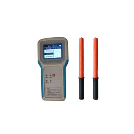
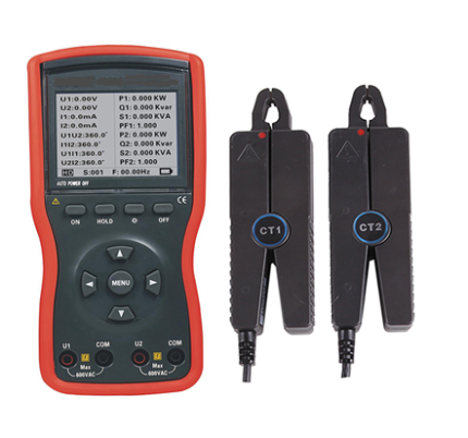
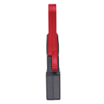
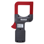
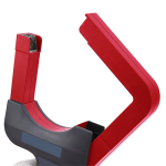
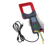
GAOTek Power Meter for Caliber with 3 Phase (High Precision) is a specialized device designed to accurately measure electrical power in three-phase power systems. Commonly used in industrial and commercial settings where three-phase power distribution is prevalent. High precision ensures accurate and reliable measurements of various electrical parameters. Designed and manufactured for measuring three phase AC voltage, current, leakage current, phase between current and voltage, phase between phase voltage, frequency, power energy, phase sequence, active power, reactive power, apparent power.
Technical Specifications
| Power Supply | DC 6 V (1.5 V x 4) |
| Clamp Size | 3.14 in × 3.41 in (80 mm × 80 mm) can clamp electric cable of 3.14 in (80 mm) diameter, or 3.77 in × 0.15 in (96 mm × 4 mm) flat cable and steel earth wires |
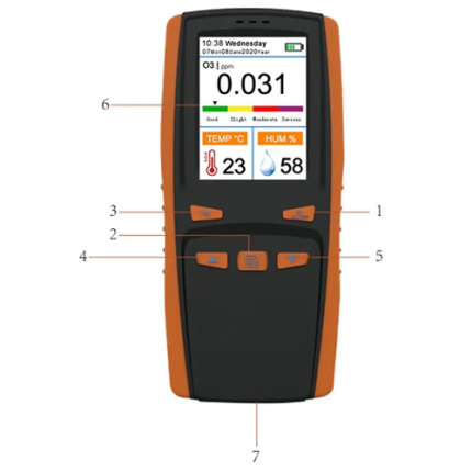
| Display mode | LCD: 128 dots × 64 dots; Display area: 1.69 in × 1.14 in (43 mm × 29 mm) |
| Range | Current: AC 0.00 mA to 1200 APower: AC 0.5 W to 720 KW
Voltage: AC 0 to 600 V Frequency: 25 Hz to 100 Hz Phase: 0.0° to 360.0° Power Factor: 0.3 to 1.0 (Capacitive or sensual) Electric energy: 0.0000 KWh to 72000 KWh |
| Resolution | Current: 0.01 mAPower: 0.01 W
Voltage: 0.01 V frequency: 0.1 Hz Phase: 0.1° Power Factor: 0.001 Electric energy: 0.0001 KWh |
| Data Storage | 200 sets, “FULL” symbol indicate the memory is full |
| Automatic Shutdown | Automatically shuts down about 15 minutes after power on to reduce battery consumption |
| Working Temperature | 14 °F to 104 °F (-10 °C to 40 °C) Humidity: 80 % RH |
| Storage Temperature | 14 °F to 140 °F (-10 °C to 60 °C) Humidity: below 70 % RH |
| Frequency | 50 Hz ,60 Hz automatic identification |
| Data Hold | “HOLD” symbol appears |
| Overflow | “OLA” symbol display |
| Sample Rate | 0.5 times/second |
| Safety Specifications | IEC1010-1, IEC1010-2-032, 2 class of pollution, CAT Ⅲ(600 V) |
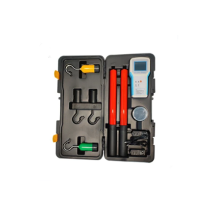
| Weight | 2.20 lb (1 kg) (with batteries and accessories) |
| Dimension | 10.82 in × 5.70 in × 1.57 in (275 mm × 145 mm × 40 mm) |