Description
Overview
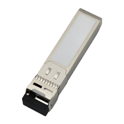
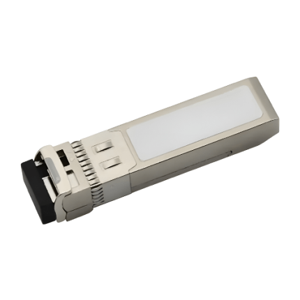
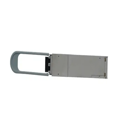
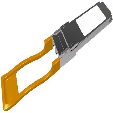
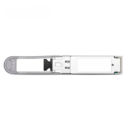
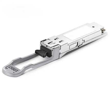
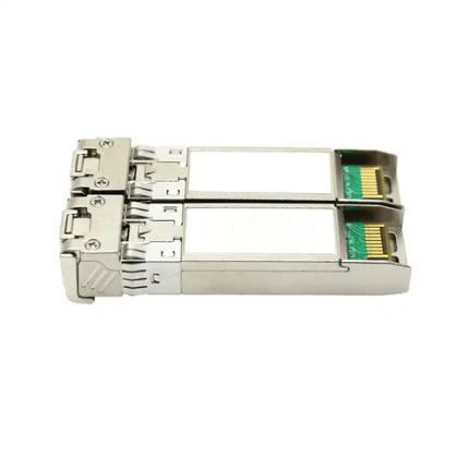
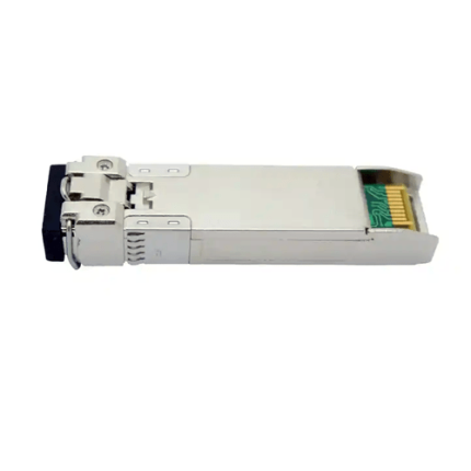
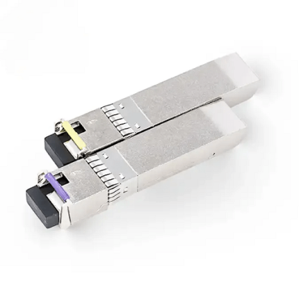
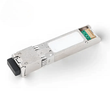
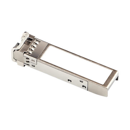
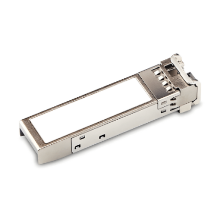
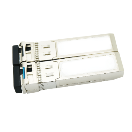
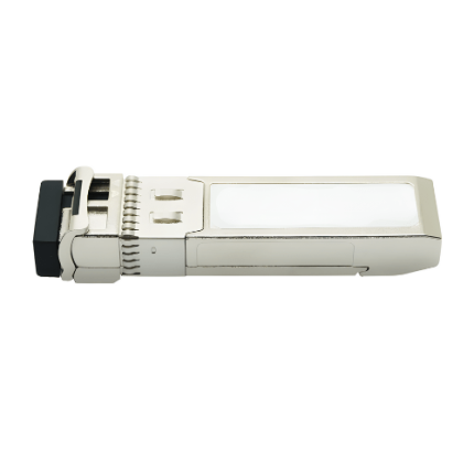
This 10 Gigabit 1270nm and 1330nm SFP+ BIDI Transceiver is used with single mode optical fiber to reach up to 24.85 miles (40km) transmission distance. This Bidirectional enhanced small form-factor pluggable (SFP+ BIDI) transceiver offers high speed communication up to 11.3 Gb/s. It complies with 802.3ae 10GBASE-ER/EW, SFF-8472, SFF-8431 and RoHS standards. It provides a unique enhanced digital diagnostic monitoring interface.
Features:
-
- Up to 24.85 miles (40km) transmission
- 1270nm DFB laser and PIN receiver
- 1330nm DFB laser and PIN receiver
- EEPROM with Serial ID Functionality
- Single +3.3V power supply
- Compliant with SFP+ MSA with LC connector
- Metal enclosure, for lower EMI
- Power dissipation <1.0W
- Management specifications compliant with SFF 8472
- 2-wire interface with integrated Digital Diagnostic monitoring
- Commercial Case operating temperature range from 32 °F to 158°F (0°C to +70°C)
- Industrial Case operating temperature range from -40 °F to 185 °F (-40°C to +85°C)
Technical Specifications:
| Protocol | 2-Wire Serial communication Protocol | |
| Working Range | Up to 24.85 miles (40km) | |
| Memory | 256-byte memory map in EEPROM | |
| Standards | SFF-8431 and SFF-8472,
RoHS compliant. 802.3ae 10GBASE-ER/EW. |
|
| Data rate | 10Gb/s | |
| Wavelength | 1270nm,1330nm | |
| Fiber Optic Cable | 9/125um | |
| Transmitter | DFB | |
| Receiver | PIN | |
| Connector | LC | |
| Transmitter output optical Power | 0 dBm to 5 dBm
-30 dBm(Laser OFF) |
|
| Receiver Sensitivity | -15 dBm | |
| Receiver Input Saturation Power | -0.5 dBm | |
| Supply Voltage | 3.3V | |
| Transmitter Input Differential Impedance | 100Ω | |
| Dimensions | 2.3in x 0.54in x 0.49in (L 58.4mm x W13.7mm x H 12.6mm) | |
| Relative Humidity | 5% to 95% | |
| Storage Temperature | -40 °F to 185 °F (-40°C to 85°C) | |
|
Case Operating Temperature |
Commercial | 32 °F to 158°F (0°C to +70°C)
|
| Industrial | -40 °F to 185 °F (-40°C to +85°C)
|
|
Additional Information:
Applications
Ideal to be used on applications such as
- 10G SONET/SDH, OTU2/2e
- 10GBASE-BX & 10GBASE-ER/EW
Test Pattern:
- Measured with a PRBS 231 -1 and BER<10-12 with data rate 10.3125Gb/s:
PRBS31 test pattern represents a pseudorandom binary sequence with a repetition period of 231 -1. The sequence is defined in IEEE STD 802.3.ae
BER<10-12 test represents bit error rate testing provides a measurable and useful indication of the performance of the system
- Case operating temperature is measured without airflow.
Ordering Information:
| Product ID | Media | Wavelength
(nm) |
Transmission Distance
Miles(km) |
Temperature Range | Supply Current |
| GAO-SFPPBD-103 | Single-mode fiber | 1270TX/1330 RX | 24.85miles (40km) | Commercial
32 °F to 158°F (0°C to +70°C) |
300mA |
| GAO-SFPPBD-103A | Single-mode fiber | 1330TX/1270RX | 24.85miles (40km) | Commercial
32 °F to 158°F (0°C to +70°C) |
300mA |
| GAO-SFPPBD-103B | Single mode fiber | 1270TX/1330 RX | 24.85miles (40km) | Industrial
-40 °F to 185 °F (-40°C to +85°C) |
300mA |
| GAO-SFPPBD-103C | Single-mode fiber | 1330TX/1270 RX | 24.85miles (40km)) | Industrial
-40 °F to 185 °F (-40°C to +85°C)
|
300mA |
Digital Diagnostics Functions:
- GAOTek GAO-SFPPBD-103 series transceivers support the 2-wire serial communication protocol as defined in the SFP MSA.
- Additionally, GAOTek SFP+ Transceivers provide a unique enhanced digital diagnostic monitoring interface which allows real-time access to device operating parameters such as transmitter optical power, receiver optical power, transceiver temperature, transceiver supply voltage and laser bias current. It defines an alarm system and warning flags, which alerts the end users when particular operating parameters are outside of a factory set normal range.
- Standard SFP+ Serial id provides access to identification information that describes the transceiver’s capabilities, standard interfaces, manufacturer and other information.
- SFP+ MSA defines a 256-byte memory map in EEPROM that is accessible over a 2 wire serial interface at the 8 bit address 1010000X (A0h).
- The operating and diagnostics information is monitored and reported by a Digital Diagnostics Transceiver Controller (DDTC) inside the transceiver, which is accessed through a 2-wire serial interface. The memories are organized as a series of 8-bit data words that can be addressed individually or sequentially
Electrical characteristics:
| Parameter | Symbol | Min | Type | Max | Unit |
| Transmitter | |||||
| Differential line input Impedance | RIN | 85 | 100 | 115 | Ω |
| Differential Data Input Voltage | VDT | 180 | 700 | mVp-p | |
| Transmit Disable Voltage-High | VDisH | 2 | Vcc+0.3 | V | |
| Transmit Disable Voltage-Low | VDisL | -0.3 | 0.8 | V | |
| Transmit Fault Output -High | VFaultH | 2.4 | Vcc | V | |
| Transmit Fault Output-Low | VFaultL | -0.3 | 0.8 | V | |
| Receiver | |||||
| Differential data output Voltage | VDR | 300 | 850 | mVp-p | |
| Differential line Output Impedance | ROUT | 80 | 100 | 120 | ohm |
| Receiver LOS Pull up Resistor | RLOS | 4.7 | 10 | KOhm | |
| Data Output Rise/Fall time | tr/tf | 38 | ps | ||
| LOS Assert Level | VLOS fault | Vcc-1.3 | VccHOST | V | |
| LOS De-assert Level | VLOS norm | Vee | Vee+0.8 | V |
Optical Characteristics:
| Parameter | Symbol | Min | Type | Max | Unit |
| Transmitter | |||||
| Average Launched Power | PO | 0 | 5 | dBm | |
| Average Launched Power(Laser Off | Poff | -30 | dBm | ||
| Center Wavelength Range | λC | 1260 | 1270 | 1280 | nm |
| 1320 | 1330 | 1340 | nm | ||
| Optical Extinction Ratio | ER | 3.5 | dB | ||
| Spectral Width(-20dB) | σ | 1 | nm | ||
| Output Eye Mask | Compliant with IEEE 802.3ae | ||||
| Side-mode Supression ratio | SMSR | 30 | dB | ||
| Receiver | |||||
| Receiver Sensitivity | Psen | -15 | dBm | ||
| Input Optical Wavelength | λIN | 1320 | 1330 | 1340 | nm |
| 1260 | 1270 | 1280 | nm | ||
| Input Saturation Power (Overload) | Psat | 0.5 | dBm | ||
| LOS Assert | LOSA | -30 | dBm | ||
| LOS De -Assert | LOSD | -17 | dBm | ||
| LOS Hysteresis | 0.5 | 5 | dB | ||
PIN out Diagram:

PIN Descriptions:
| Pin | Symbol | Name/Description | Note |
| 1 | VEET | Transmitter Ground (Common with Receiver Ground) | 1 |
| 2 | TFault | Transmitter Fault | 2 |
| 3 | TDis | Transmitter Disable. | 3 |
| 4 | SDA | 2-wire Serial Interface Data Line | 4 |
| 5 | SCL | 2-wire Serial Interface Clock Line | 4 |
| 6 | MOD_ABS | Module Absent. Grounded within the module | 5 |
| 7 | RS0 | Rate Select 0. |
6 |
| 8 | LOS | Loss of Signal indication. Logic 0 indicates normal operation | 7 |
| 9 | RS1 | No connection required | 1 |
| 10 | VEER | Receiver Ground (Common with Transmitter Ground) | 1 |
| 11 | VEER | Receiver Ground (Common with Transmitter Ground) | 1 |
| 12 | RD- | Receiver Inverted DATA out. AC coupled | |
| 13 | RD+ | Receiver Non-inverted DATA out. AC coupled | |
| 14 | VEER | Receiver Ground (Common with transmitter Ground) | 1 |
| 15 | VCCR | Receiver power Supply | |
| 16 | VCCT | Transmitter Power supply | |
| 17 | VEET | Transmitter Ground (Common with receiver Ground) | 1 |
| 18 | TD+ | Transmitter Non-Inverted DATA in. AC Coupled. | |
| 19 | TD- | Transmitter Inverted DATA in.AC Coupled. | |
| 20 | VEET | Transmitter Ground | 1 |
Notes:
- Circuit ground is internally isolated from ground.
- TFault is an open collector or drain output.
- This should be pulled up with a 4.7k -10k ohms resistor on the host board if intended for use.
- Pull up voltage should be between 2.0V to Vcc +0.3V.
- High output indicates a transmitter fault caused by either the TX bias current or the TX output power exceeding the preset alarm thresholds.
- Low output indicates normal operation. In the low state output is pulled to <0.8V
- Laser output disabled when it is open or TDis > 2.0V, enabled on TDis < 0.8V.
- Should be pulled up with 4.7kΩ to 10kΩ on host board to a voltage between 2.0V and 3.6V.
- MOD_ABS pulls the line low to indicate the module is plugged in.
- Internally pulled down per SFF-8431
- Loss of signal is open collector output.
- This should be pulled up with 4.7 kΩ to 10 kΩ on host board to a voltage between 2.0V and 3.6V.
- Logic 0 indicates normal operation.
- Logic 1 indicates loss of signal.
Host – Transceiver Interface Block Diagram:

Regulatory Compliance:
| Feature | Reference | Performance |
| Laser Eye Safety | FDA 21CFR 1040.10, 1040.11 IEC/EN 60825-1,2 | Class 1 laser product |
| Component Recognition | IEC/EN 60950, UL | Compatible with standards |
| ROHS | 2002/95/EC | Compatible with standards |
| Electrostatic discharge(ESD) | IEC/EN 61000-4-2 | Compatible with standards |
| EMC | EN61000-3 | Compatible with standards |
| Electromagnetic Interference(EMI) | FCC Part 15 Class B EN 55022 Class B (CISPR 22A) | Compatible with standards |