Description
Key Features
- Compliant with SFF-8472 and ROHS-6
- Up to 12.4 Miles (20Km) transmission distance
- 125 Gbps data rate
- DFB laser transmitter and PIN photo-detector
- EEPROM with Serial ID Functionality
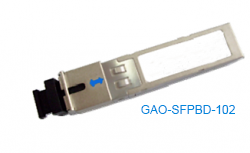
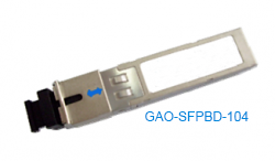
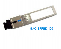
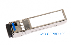
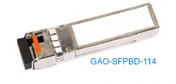
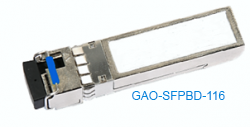
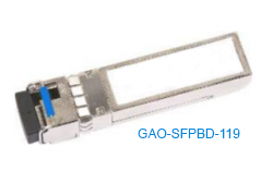
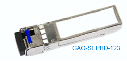
- SFP package with LC/UPC receptacle connect
- Support Digital Diagnostic Monitoring interface
- Single + 3.3V Power Supply and TTL Logic Interface
- Class 1 Product which comply with the requirements of IEC 60825-1
- Case operating temperature range from 32°F to 158°F (0°C to +70°C)
Technical Specifications
| Protocol | 2-wire serial communication protocol |
| Standard | Class 1 Product which complies with the requirements of IEC 60825-1.
SFF-8472 ROHS-6 |
| Working Range | Up to 12.4 Miles (20Km) |
| Data rate | 3.125 Gb/s |
| Wavelength | CWDM |
| Transmitter Extinction Ratio | 8.2 dB |
| Transmitter Off Output Power | -45dBm |
| Transmitter Differential Line Input Impedance | 90-110 Ω |
| Receiver Sensitivity | -18dBm |
| Receiver Input Saturation Power(Overload) | -1 dBm |
| Supply Voltage | -0.3 to 3.7V |
| Dimensions | 2.29in*0.54in*0.33 in (L 58.4mm*W 13.9mm*H 8.5mm) |
| Storage Ambient Humidity | 5% to 95% |
| Storage Temperature | -40°F to 185°F (-40°C to 85°C) |
| Case Operating Temperature | 32°F to 158°F (0°C to +70°C) |
Product Selection
| Wavelength | Clasp Color code |
| 1270 nm | Gray |
| 1290 nm | Gray |
| 1310 nm | Gray |
| 1330 nm | Purple |
| 1350 nm | Blue |
| 1370 nm | Green |
| 1390 nm | Yellow |
| 1410 nm | Orange |
| 1430 nm | Red |
| 1450 nm | Brown |
| 1470 nm | Gray |
| 1490 nm | Purple |
| 1510 nm | Blue |
| 1530 nm | Green |
| 1550 nm | Yellow |
| 1570 nm | Orange |
| 1590 nm | Red |
| 1610 nm | Brown |
PIN Descriptions:


Notes:
- TX Fault is an open collector/drain output, which should be pulled up with a 4.7K – 10KΩ resistor on the host board. Pull up voltage between 2.0V and VccT, R+0.3V. When high, output indicates a laser fault of some kind.
Low indicates normal operation. In the low state, the output will be pulled to < 0.8V.
- TX disable is an input that is used to shut down the transmitter optical output. It is pulled up within the module with a 4.7 – 10 K Ω resistor. It’s states are:
- Low (0 – 0.8V): Transmitter on
- (>0.8, < 2.0V): Undefined
- High (2.0 – 3.465V): Transmitter Disabled
- Open: Transmitter Disabled
- Mod-Def 0, 1, 2. These are the module definition pins. They should be pulled up with a 4.7K – 10KΩresistor on the host board. The pull-up voltage shall be VccT or VccR (see Section IV for further details). Mod-Def 0 is grounded by the module to indicate that the module is present Mod-Def 1 is the clock line of two wire serial interface for serial ID Mod-Def 2 is the data line of two wire serial interface for serial ID
- LOS (Loss of Signal) is an open collector/drain output, which should be pulled up with a 4.7K – 10KΩ resistor.
Pull up voltage between 2.0V and VccT, R+0.3V. When high, this output indicates the received optical power is below the worst-case receiver sensitivity (as defined by the standard in use). Low indicates normal operation. In the low state, the output will be pulled to < 0.8V.
- VeeR and VeeT may be internally connected within the SFP module.
- RD-/+: These are the differential receiver outputs. They are AC coupled 100Ω differential lines which should be terminated with 100Ω (differential) at the user SERDES. The AC coupling is done inside the module and is thus not required on the host board. The voltage swing on these lines will be between 370 and 2000 mV differential (185 – 1000 mV single ended) when properly terminated.
- VccR and VccT are the receiver and transmitter power supplies. They are defined as 3.3V ±5% at the SFP connector pin. Maximum supply current is 300mA. Recommended host board power supply filtering is shown below. Inductors with DC resistance of less than 1 ohm should be used in order to maintain the required voltage at the SFP input pin with 3.3V supply voltage. When the recommended supply-filtering network is used, hot plugging of the SFP transceiver module will result in an inrush current of no more than 30mA greater than the steady state value. VccR and VccT may be internally connected within the SFP transceiver module.
- TD-/+: These are the differential transmitter inputs. They are AC-coupled, differential lines with 100Ω differential termination inside the module. The AC coupling is done inside the module and is thus not required on the host board. The inputs will accept differential swings of 500 – 2400 mV (250 – 1200 mV single-ended), though it is recommended that values between 500 and 1200 mV differential (250 – 600 mV single-ended) be used for best EMI performance
Digital Diagnostic Functions
GAOTek GAO-SFPCB-101 transceivers support the 2-wire serial communication protocol as defined in the SFP MSA. It is very closely related to the E2PROM defined in the GBIC standard, with the same electrical specifications. The standard SFP serial ID provides access to identification information that describes the transceiver’s capabilities, standard interfaces, manufacturer, and other information.
Additionally, GAOTek SFP transceivers provide a unique enhanced digital diagnostic monitoring interface, which allows real-time access to device operating parameters such as transceiver temperature, laser bias current, transmitted optical power, received optical power and transceiver supply voltage .It also defines a sophisticated system of alarm and warning flags, which alerts end-users when particular operating parameters are outside of a factory set normal range.
The SFP MSA defines a 256-byte memory map in E2PROM that is accessible over a 2-wire serial interface at the 8 bit address 1010000X (A0h). The digital diagnostic monitoring interface makes use of the 8 bit address 1010001X (A2h), so the originally defined serial ID memory map remains unchanged. The interface is identical to, and is thus fully backward compatible with both the GBIC Specification and the SFP Multi Source Agreement.
The operating and diagnostics information is monitored and reported by a Digital Diagnostics Transceiver Controller (DDTC) inside the transceiver, which is accessed through a 2-wire serial interface. When the serial protocol is activated, the serial clock signal (SCL, Mod Def 1) is generated by the host. The positive edge clocks data into the SFP transceiver into those segments of the E2PROM that are not write-protected. The negative edge clocks data from the SFP transceiver. The serial data signal (SDA, Mod Def 2) is bi-directional for serial data transfer. The host uses SDA in conjunction with SCL to mark the start and end of serial protocol activation. The memories are organized as a series of 8-bit data words that can be addressed individually or sequentially.
Digital diagnostics for the GAO-SFPCB-101 are internally calibrated by default.
Recommended Circuit Schematic

Mechanical Specifications

Applications
- Switch to Switch Interface
- Gigabit Ethernet
- Switched Backplane Applications
- Router/Server Interface
- Other Optical Links