
Description
Overview:
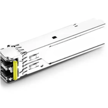
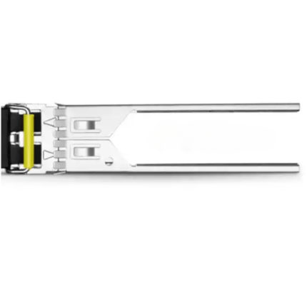
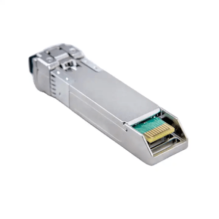
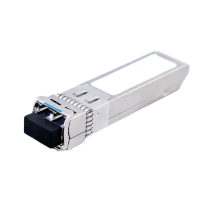
This 10 Gigabit SFP+ (enhanced small form-factor pluggable) Tunable Transceiver is used with single mode optical fiber to reach up to 49.72 miles (80km) transmission distance. It has a C-band-tunable integrated Mach-Zehnder (MZ) laser type transmitter and an APD transceiver. It provides a unique enhanced digital diagnostic monitoring interface. It complies with the ITU-T G.698.1 standard.
Key Features:
-
- Monolithically integrated full C-band tunable transmitter and APD receiver.
- Up to 49.72 miles (80km) transmission distance
- Single 3.3V power supply
- Compliant with SFP+ MSA with LC connector
- Metal enclosure, for lower EMI
- 50 GHz ITU channel spacing with integrated wavelength locker.
- Hot-pluggable SFP+ footprint
- 2-wire interface with integrated Digital Diagnostic monitoring
- Management specifications compliant with SFF-8472 V11.3& SFF-8690 V1.4
- Power dissipation <1.65W
- Case operating temperature range from 23°F to 158°F (-5°C to +70°C)
Technical Specifications:
| Protocol | 2-Wire Serial communication Protocol |
| Working Range | Up to 49.72 miles (80km) |
| Memory | 256-byte memory map in EEPROM |
| Standards | SFF-8472 V11.3 and SFF-8690 V1.4. ITU-T G.698.1. |
| Data rate | 10 Gb/s |
| Single Mode Fiber | 9/125um |
| Transmitter | C-band-tunable integrated MZ laser |
| Receiver | APD |
| Connector | LC |
| Center Wavelength Spacing | 50 GHz |
| Transmitter output optical Power | -1 dBm to -3 dBm |
| Receiver Input Saturation Power | -6 dBm |
| Supply Voltage | 3.3V |
| Transmitter Input Differential Impedance | 100Ω |
| Dimensions | 2.26in x 0.54in x 0.47in (L 57.3mm x W13.7mm x H 11.9mm) |
| Relative humidity | 5% to 85% |
| Storage Temperature | -40 °F to 185 °F (-40°C to 85°C) |
| Case Operating Temperature | 23 °F to 158 °F (-5°C to 70°C) |
Additional Information:
Applications
Ideal to be used on applications such as
- DWDM SONET OC-192&SDH STM-64
- DWDM 80KM 10G Fiber Channel
- DWDM 10GBASE-ZR/ZW 10G Ethernet
Ordering Information:
| Product ID | Media | Wavelength | Transmission Distance | Temperature Range | Supply Current |
| GAO-SFPPT-101
|
Single-mode fiber | C-band Tunable module | 49.72miles(80km) | 23°F to 158°F (-5°C to +70°C)
|
500 mA |
Wavelength:
- When a tunable module is plugged in for the first time, it will go to a default wavelength 1568.36nm, compatible with channel range from 1 to 99.
- When the module is power cycled it will automatically go to the last channel, or when the Tx_Disable asserted and then re-enabled, the module returns to the last channel.
Wavelength Table
| Channel | Wavelength(nm) | Frequency(THZ) | Channel | Wavelength(nm) | Frequency(THZ) |
| 1 | 1568.36 | 191.15 | 51 | 1548.11 | 193.65 |
| 2 | 1567.95 | 191.20 | 52 | 1547.72 | 193.70 |
| 3 | 1567.54 | 191.25 | 53 | 1547.32 | 193.75 |
| 4 | 1567.13 | 191.30 | 54 | 1546.92 | 193.80 |
| 5 | 1566.72 | 191.35 | 55 | 1546.52 | 193.85 |
| 6 | 1566.31 | 191.40 | 56 | 1546.12 | 193.90 |
| 7 | 1565.90 | 191.45 | 57 | 1545.72 | 193.95 |
| 8 | 1565.50 | 191.50 | 58 | 1545.32 | 194.00 |
| 9 | 1565.09 | 191.55 | 59 | 1544.92 | 194. 05 |
| 10 | 1564.68 | 191.60 | 60 | 1544.53 | 194. 10 |
| 11 | 1564.27 | 191.65 | 61 | 1544.13 | 194. 15 |
| 12 | 1563.86 | 191.70 | 62 | 1543.73 | 194. 20 |
| 13 | 1563.45 | 191.75 | 63 | 1543.33 | 194. 25 |
| 14 | 1563.05 | 191.80 | 64 | 1542.94 | 194. 30 |
| 15 | 1562.64 | 191.85 | 65 | 1542.54 | 194. 35 |
| 16 | 1562.23 | 191.90 | 66 | 1542.14 | 194. 40 |
| 17 | 1561.83 | 191.95 | 67 | 1541.75 | 194. 45 |
| 18 | 1561.42 | 192.00 | 68 | 1541.35 | 194. 50 |
| 19 | 1561.01 | 192.05 | 69 | 1540.95 | 194. 55 |
| 20 | 1560.61 | 192.10 | 70 | 1540.56 | 194. 60 |
| 21 | 1560.20 | 192.15 | 71 | 1540.16 | 194. 65 |
| 22 | 1559.79 | 192.20 | 72 | 1539.77 | 194. 70 |
| 23 | 1559.39 | 192.25 | 73 | 1539.37 | 194. 75 |
| 24 | 1558.98 | 192.30 | 74 | 1538.98 | 194. 80 |
| 25 | 1558.58 | 192.35 | 75 | 1538.58 | 194. 85 |
| 26 | 1558.17 | 192.40 | 76 | 1538.19 | 194. 90 |
| 27 | 1557.77 | 192.45 | 77 | 1537.79 | 194. 95 |
| 28 | 1557.36 | 192.50 | 78 | 1537.40 | 195. 00 |
| 29 | 1556.96 | 192.55 | 79 | 1537.00 | 195. 05 |
| 30 | 1556.55 | 192.60 | 80 | 1536.61 | 195. 10 |
| 31 | 1556.15 | 192.65 | 81 | 1536.22 | 195. 15 |
| 32 | 1555.75 | 192.70 | 82 | 1535.82 | 195. 20 |
| 33 | 1555.34 | 192.75 | 83 | 1535.43 | 195. 25 |
| 34 | 1554.94 | 192.80 | 84 | 1535.04 | 195. 30 |
| 35 | 1554.54 | 192.85 | 85 | 1534.64 | 195. 35 |
| 36 | 1554.13 | 192.90 | 86 | 1534.25 | 195. 40 |
| 37 | 1553.73 | 192.95 | 87 | 1533.86 | 195. 45 |
| 38 | 1553.33 | 193.00 | 88 | 1533.47 | 195. 50 |
| 39 | 1552.93 | 193.05 | 89 | 1533.07 | 195. 55 |
| 40 | 1552.52 | 193.10 | 90 | 1532.68 | 195. 60 |
| 41 | 1552.12 | 193.15 | 91 | 1532.29 | 195. 65 |
| 42 | 1551.72 | 193.20 | 92 | 1531.90 | 195. 70 |
| 43 | 1551.32 | 193.25 | 93 | 1531.51 | 195.75 |
| 44 | 1550.92 | 193.30 | 94 | 1531.12 | 195.80 |
| 45 | 1550.52 | 193.35 | 95 | 1530.72 | 195.85 |
| 46 | 1550.12 | 193.40 | 96 | 1530.33 | 195.90 |
| 47 | 1549.72 | 193.45 | 97 | 1529.94 | 195.95 |
| 48 | 1549.32 | 193.50 | 98 | 1529.55 | 196.00 |
| 49 | 1548.91 | 193.55 | 99 | 1529.16 | 196.05 |
| 50 | 1548.51 | 193.60 |
Test pattern:
- Measured with BER<10-4 @ data rate 10.709 Gb/s,11.1 Gb/s and 11.3 Gb/s and BER<10-12 @ data rate 9.95,10.3,10.5 Gb/s
BER<10-12 and BER<10-12 represents bit error rate testing provides a measurable and useful indication of the performance of the system.
- 20 – 80 % Measured with Module Compliance Test Board and OMA test pattern.
Digital Diagnostics Functions:
- GAOTek GAO-SFPPT-101 transceiver support the 2-wire serial communication protocol as defined in the SFP MSA1.
- Additionally, GAOTek SFP+ Transceivers provide a unique enhanced digital diagnostic monitoring interface which allows real-time access to device operating parameters such as transmitter optical power, receiver optical power, transceiver temperature, transceiver supply voltage and laser bias current. It defines an alarm system and warning flags, which alerts the end users when particular operating parameters are outside of a factory set normal range.
- Standard SFP+ Serial id provides access to identification information that describes the transceiver’s capabilities, standard interfaces, manufacturer and other information.
- SFP+ MSA defines a 256-byte memory map in EEPROM that is accessible over a 2 wire serial interface at the 8 bit address 1010000X (A0h).
- The operating and diagnostics information is monitored and reported by a Digital Diagnostics Transceiver Controller (DDTC) inside the transceiver, which is accessed through a 2-wire serial interface. The memories are organized as a series of 8-bit data words that can be addressed individually or sequentially
Electrical characteristics:
| Parameter | Symbol | Min | Type | Max | Unit | Note |
| Transmitter | ||||||
| Input Differential Impedance | Rin | 100 | Ω | |||
| Differential data input swing | Vin, pp | 240 | 910 | mV | ||
| Transmit Disable Voltage | VD | Vcc–1.3 | Vcc | V | ||
| Transmit Enable Voltage | VEN | Vee | Vee+ 0.8 | V | ||
| TX_FAULT Voltage-High | Vcc–1.3 | Vcc | V | |||
| TX_FAULT Voltage-Low | Vee | Vee+ 0.8 | V | |||
| Receiver | ||||||
| Differential data output swing | Vout,pp | 350 | 800 | mV | ||
| Data output rise time | tr | 30 | ps | |||
| Data output fall time | tf | 30 | ps | |||
| LOS Fault | Vcc–1.3 | VccHOST | V | 1 | ||
| LOS Normal | Vee | Vee+0.8 | V | 1 |
Notes:
- Loss of Signal is LVTTL. Logic 0 indicates normal operation; logic 1 indicates no signal detected.
Optical Characteristics:
| Parameter | Symbol | Min | Type | Max | Unit | Notes |
| Transmitter | ||||||
| Average Optical Power | POUT | -1 | 3 | dBm | ||
| Frequency stability (BOL) | ƒ c –1.5 | ƒ c +1.5 | GHz | |||
| Frequency stability (EOL) | ƒ c –2.5 | ƒ c +2.5 | GHz | |||
| Optical Extinction Ratio | ER | 8.2 | dB | |||
| Center Wavelength Spacing | 50 | GHz | ||||
| Average Launch Power(Laser off) | Poff | -30 | dBm | |||
| Output Eye Mask | IEEE 802.3ae requirements | |||||
| Side-mode Supression ratio | SMSR | 35 | dB | |||
| Receiver | ||||||
| Rx Sensitivity with dispersion 0 ps/nm | RSENS | -23 | dBm | @9.95, 10.3, 10.5Gbps | ||
| -27 | @10.709Gbps | |||||
| -27 | @11.1Gbps | |||||
| -26.5 | @11.3Gbps | |||||
| Rx Sensitivity with dispersion 0 ps/nm | RSENS | -21 | dBm | @9.95, 10.3, 10.5Gbps | ||
| -25 | @10.709Gbps | |||||
| -25 | @11.1Gbps | |||||
| -24 | @11.3Gbps | |||||
| Wavelength Range | λC | 1480 | 1580 | nm | ||
| Input Saturation Power (Overload) | Psat | -6 | dBm | |||
| LOS Assert | LOSA | -36 | dBm | |||
| LOS De -Assert | LOSD | -27 | dBm | |||
| LOS Hysteresis | 0.5 | dB | ||||
Timing parameters:
| Parameter | Symbol | Min | Type | Max | Unit | Notes |
| Time to initialize cooled module | Tstart_up | 20 | S | |||
| Channel Switch time | TchannelSwitch | 200 | ms | Any channel to any channel |
PIN out Diagram:

PIN Descriptions:
| Pin | Symbol | Name/Description | Note |
| 1 | VEET | Transmitter Ground (Common with Receiver Ground) | 1 |
| 2 | TFault | Transmitter Fault | 2 |
| 3 | TDis | Transmitter Disable. | 3 |
| 4 | SDA | 2-wire Serial Interface Data Line | 4 |
| 5 | SCL | 2-wire Serial Interface Clock Line | 4 |
| 6 | MOD_ABS | Module Absent. Grounded within the module | 5 |
| 7 | RS0 | Rate select 0 | 6
|
| 8 | LOS | Loss of Signal indication. Logic 0 indicates normal operation | 7 |
| 9 | RS1 | No connection required | 1 |
| 10 | VEER | Receiver Ground (Common with Transmitter Ground) | 1 |
| 11 | VEER | Receiver Ground (Common with Transmitter Ground) | 1 |
| 12 | RD- | Receiver Inverted DATA out. AC coupled | |
| 13 | RD+ | Receiver Non-inverted DATA out. AC coupled | |
| 14 | VEER | Receiver Ground (Common with transmitter Ground) | 1 |
| 15 | VCCR | Receiver power Supply | |
| 16 | VCCT | Transmitter Power supply | |
| 17 | VEET | Transmitter Ground (Common with receiver Ground) | 1 |
| 18 | TD+ | Transmitter Non-Inverted DATA in. AC Coupled. | |
| 19 | TD- | Transmitter Inverted DATA in.AC Coupled. | |
| 20 | VEET | Transmitter Ground | 1 |
Notes:
- Circuit ground is internally isolated from ground.
- TFault is an open collector or drain output.
- It should be pulled up with a 4.7k -10k ohms resistor on the host board if intended for use.
- Pull up voltage should be between 2.0V to Vcc +0.3V.
- High output indicates a transmitter fault caused by either the TX bias current or the TX output power exceeding the preset alarm thresholds.
- Low output indicates normal operation. In the low state output is pulled to <0.8V
- Laser output disabled when it is open or TDis > 2.0V, enabled on TDis < 0.8V.
- Should be pulled up with 4.7kΩ to 10kΩ on host board to a voltage between 2.0V and 3.6V.
- MOD_ABS pulls the line low to indicate the module is plugged in.
- Internally pull down per SFF-8431.
- Loss of signal is open collector output.
- This should be pulled up with 4.7 kΩ to 10 kΩ on host board to a voltage between 2.0V and 3.6V.
- Logic 0 indicates normal operation.
- Logic 1 indicates loss of signal.
Mechanical Specifications:
Improved Pluggable form factor specification Comply to SFF-8432

HOST-Transceiver Interface Block Diagram: