Description
Overview:
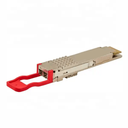
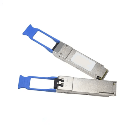
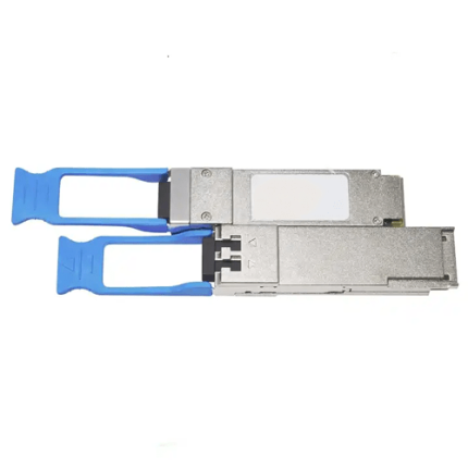
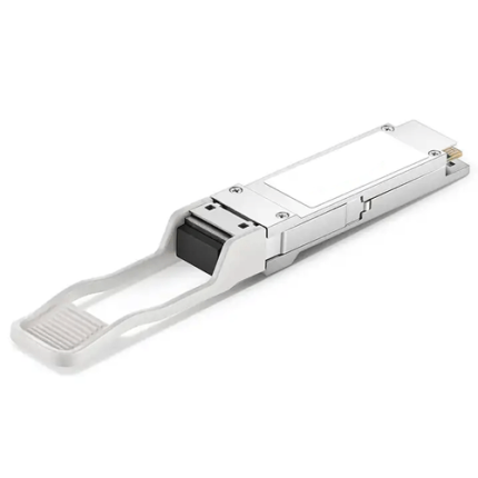
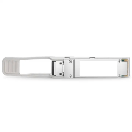
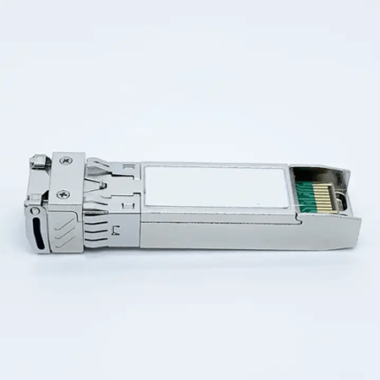
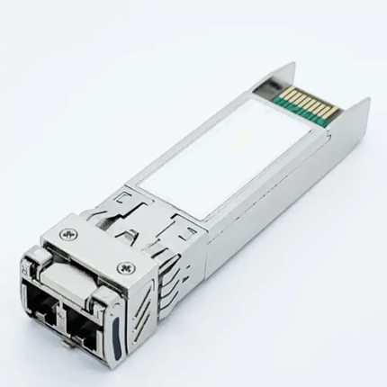
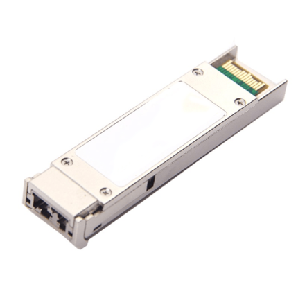
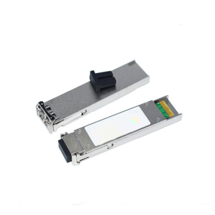
This 10 Gigabit 1490nm and 1550nm XFP Bidirectional Transceiver is used with single mode optical fiber to reach up to 49.72 miles (80km) transmission distance. It offers high speed communication rates up to 11.3 Gb/s. It has an EML type transmitter and APD type receiver. It provides a built-in Digital Diagnostics Function. It complies with small form-factor pluggable (XFP) MSA and RoHS-6 standards.
Key Features:
-
- Up to 49.72 miles (80km) transmission distance.
- 1490nm EML laser and APD receiver
- 1550nm EML laser and APD receiver
- Supports 9.95Gb/s to 11.3Gb/s bit rates
- Hot-pluggable XFP footprint.
- 2-wire interface with integrated Digital Diagnostic monitoring
- EEPROM with Serial ID Functionality
- Power dissipation<2.5W.
- XFI Loopback Mode.
- RoHS-6 Compliant (lead-free)
- Compliant with XFP MSA with LC connector
- Industrial Case operating temperature range from -40 °F to 185 °F (-40°C to 85°C)
- Commercial Case operating temperature range from 50 °F to 158 °F (-10°C to 70°C)
Technical Specifications:
| Working Range | Up to 49.72 miles (80km) | |
| Standards | As per IEEE 802.3ae requirements.
Class 1 Laser Product. XFP MSA. RoHS-6 compliant. |
|
| Memory | 256 byte EEPROM | |
| Data rate | 10Gb/s | |
| Wavelength | 1490nm ,1550nm | |
| Connector | LC | |
| Transmitter | EML | |
| Receiver | APD | |
| Fiber type | 9/125 um single-mode | |
| Transmitter output optical Power | 0 dBm to 4 dBm
-1 dBm to 3 dBm |
|
| Receiver Sensitivity | -24 dBm | |
| Receiver Input Saturation Power | -6 dBm | |
| Supply Voltage | 3.3V | |
| Maximum Power Consumption | <2.5W | |
| Transmitter Input Differential Impedance | 100Ω | |
| Dimensions | 3.07in x 0.72in x 0.45in (L 78mm x W18.3mm x H 11.4mm) | |
| Relative Humidity | 5% to 95% | |
| Storage Temperature | -40 °F to 185 °F (-40°C to 85°C) | |
| Case Operating Temperature | Industrial | -40 °F to 185 °F (-40°C to 85°C) |
| Commercial | 50 °F to 158 °F (-10°C to 70°C) | |
Additional Information:
Applications
Ideal to be used on applications such as
- 10GBASE-BX 9.953Gb/s Ethernet
- SONET OC-192 &SDH STM I-64.1
- 10GBASE-BX 10.3125Gb/s Ethernet
Ordering Information:
| Product ID | Media | Wavelength
(nm) |
Transmission Distance | Temperature Range |
| GAO-XFPBD -101
|
single-mode fiber | 1490TX/1550 RX | 49.72miles (80km) | Commercial
50 °F to 158 °F (-10°C to 70°C) |
| GAO-XFPBD -101A
|
single-mode fiber | 1550TX/1490 RX | 49.72miles (80km) | Commercial
50 °F to 158 °F (-10°C to 70°C) |
| GAO-XFPBD -101B
|
single-mode fiber | 1490TX/1550 RX | 49.72miles (80km) | Industrial
-40 °F to 185 °F (-40°C to +85°C) |
| GAO-XFPBD -101C
|
single-mode fiber | 1550 TX/1490 RX | 49.72miles (80km) | Industrial
-40 °F to 185 °F (-40°C to +85°C) |
Digital Diagnostics Functions:
- GAOTek GAO- XFPBD -101 series transceiver support the 2-wire serial communication protocol as defined in the XFP MSA.
- Additionally, GAOTek XFP Transceivers provide a unique enhanced digital diagnostic monitoring interface which allows real-time access to device operating parameters such as transmitter optical power, receiver optical power, transceiver temperature, transceiver supply voltage and laser bias current. It defines an alarm system and warning flags, which alerts the end users when particular operating parameters are outside of a factory set normal range.
- Standard XFP Serial id provides access to identification information that describes the transceiver’s capabilities, standard interfaces, manufacturer and other information.
- XFP MSA defines a 256-byte memory map in EEPROM that is accessible over a 2 wire serial interface at the 8 bit address 1010000X (A0h).
- The operating and diagnostics information is monitored and reported by a Digital Diagnostics Transceiver Controller (DDTC) inside the transceiver, which is accessed through a 2-wire serial interface. The memories are organized as a series of 8-bit data words that can be addressed individually or sequentially
Electrical characteristics:
| Parameter | Symbol | Min | Type | Max | Unit | Note |
| Module Total Power | 2.5 | W | 1 | |||
| Supply Current-1.8V supply | Icc2 | 200 | mA | |||
| Supply Current-3.3V supply | Icc3 | 650 | mA | |||
| XFP Interrupt, Mod_NR | Vol | 0 | 0.4 | V | ||
| Voh | VccHOST -0.5 | VccHOST +0.3 | V | |||
| P_Down/RST | Vil | -0.3 | 0.8 | V | ||
| Vih | 2.0 | Vcc3+0.3 | V | |||
| Interrupt Assert Delay | Interrupt_on | 200 | ms | |||
| Interrupt Negate Delay | Interrupt_off | 500 | us | |||
| Mod_NR Assert / Negate Delay | 1 | ms | ||||
| P-Down reset time | 10 | us | ||||
| Transmitter | ||||||
| Input Differential Impedance | Rin | 80 | 100 | 120 | Ω | 2 |
| Single ended data input swing | Vin, pp | 120 | 820 | mV | ||
| Transmit Disable Voltage | VD | 2.0 | Vcc | V | 3 | |
| Transmit Enable Voltage | Ven | GND | GND+ 0.8 | V | ||
| Receiver | ||||||
| Differential Output Impedance | Rout | 80 | 100 | 120 | Ω | 4 |
| Differential data output swing | Vout,pp | 340 | 850 | mV | ||
| Data output rise time | tr | 38 | ps | 5 | ||
| Data output fall time | tf | 38 | ps | 5 | ||
| LOS Fault | VLOS fault | Vcc–0.5 | VccHOST | V | 6 | |
| LOS Normal | VLOS norm | GND | GND+0.5 | V | 6 |
Notes:
- Maximum total power value is specified across the full temperature and voltage range.
- After internal AC coupling.
- Open circuit.
- Into 100 ohms differential termination.
- These are unfiltered 20-80% values
- Loss of Signal is open collector to be pulled up with a 4.7kΩ – 10kΩ resistor to 3.15 – 3.6V.
- Logic 0 indicates normal operation.
- Logic 1 indicates no signal detected.
Optical Characteristics:
| Parameter | Symbol | Min | Type | Max | Unit | Note |
| Transmitter | ||||||
| Average Launched Power | PO | 0 | – | 4 | dBm | GAO-XFPBD -101B
|
| -1 | – | 3 | dBm | GAO-XFPBD -101C
|
||
| Centre Wavelength Range | λ | 1480 | 1490 | 1500 | nm | GAO-XFPBD -101B
|
| 1540 | 1550 | 1560 | nm | GAO-XFPBD -101C
|
||
| Side mode Suppression ratio | SMSR | 30 | – | – | dB | |
| Optical Extinction Ratio | ER | 6 | – | – | dB | |
| Average Launch power of transmitter | POFF | – | – | -45 | dBm | |
| Spectrum Bandwidth(-20dB) | σ | – | – | 1 | nm | |
| Output Eye Mask | Compliant with IEEE 802.3ae requirements | |||||
| Receiver | ||||||
| Receiver Sensitivity | RSENS | -24 | dBm | |||
| Input Optical Wavelength | λIN | 1480 | 1490 | 1500 | nm | GAO-XFPBD -101C
|
| 1540 | 1550 | 1560 | nm | GAO-XFPBD -101B
|
||
| Input Saturation Power (Overload) | Psat | -6 | dBm | |||
| Receiver Reflectance | Rrx | – | -27 | dB | ||
| LOS Assert | LOSA | -38 | – | dBm | ||
| LOS De -Assert | LOSD | – | – | -25 | dBm | |
| LOS Hysteresis | 0.5 | 4 | dB | |||
PIN Diagram:

PIN Descriptions:
| Pin | Logic | Symbol | Name/Description | Note |
| 1 | GND | Module Ground | 1 | |
| 2 | VEE5 | Optional –5.2 Power Supply – Not required | ||
| 3 | LVTTL-I | Mod-Desel | Module De-select; When held low allows the module to respond to 2-wire serial interface commands | |
| 4 | LVTTL-O | Interrupt | Interrupt (bar); Indicates presence of an important condition which can be read over the serial 2-wire interface | 3 |
| 5 | LVTTL-I | TX_DIS | Transmitter Disable; Transmitter laser source turned off | |
| 6 | VCC5 | +5 Power Supply | ||
| 7 | GND | Module Ground | 1 | |
| 8 | VCC3 | +3.3V Power Supply | ||
| 9 | VCC3 | +3.3V Power Supply | ||
| 10 | LVTTL-I | SCL | Serial 2-wire interface clock | |
| 11 | LVTTL-I/O | SDA | Serial 2-wire interface data line | 3 |
| 12 | LVTTL-O | Mod_Abs | Module Absent; Indicates module is not present. Grounded in the module. | 3 |
| 13 | LVTTL-O | Mod_NR | Module Not Ready; GAOTek defines it as a logical OR between RX_LOS and Loss of Lock in TX/RX. | 3 |
| 14 | LVTTL-O | RX_LOS | Receiver Loss of Signal indicator | 3 |
| 15 | GND | Module Ground | 1 | |
| 16 | GND | Module Ground | 1 | |
| 17 | CML-O | RD- | Receiver inverted data output | |
| 18 | CML-O | RD+ | Receiver non-inverted data output | |
| 19 | GND | Module Ground | 1 | |
| 20 | VCC2 | +1.8V Power Supply – Not required | ||
| 21 | LVTTL-I | P_Down/RST | Power Down; When high, places the module in the low power stand-by mode and on the falling edge of P_Down initiates a module reset
|
|
| Reset; The falling edge initiates a complete reset of the module including the 2-wire serial interface, equivalent to a power cycle. | ||||
| 22 | VCC2 | +1.8V Power Supply – Not required | ||
| 23 | GND | Module Ground | 1 | |
| 24 | PECL-I | RefCLK | Reference Clock non-inverted input, AC coupled on the host board –Not required | 2 |
| 25 | PECL-I | RefCLK- | Reference Clock inverted input, AC coupled on the host board – Not required | 2 |
| 26 | GND | Module Ground | 1 | |
| 27 | GND | Module Ground | 1 | |
| 28 | CML-I | TD- | Transmitter inverted data input | |
| 29 | CML-I | TD+ | Transmitter non-inverted data input | |
| 30 | GND | Module Ground | 1 |
Notes:
- Module circuit ground is isolated from module chassis ground within the module.
- A Reference Clock input is not required .If present, it will be ignored.
- Open collector; should be pulled up with 4.7kΩ – 10kΩ on host board to a voltage between 3.15V and 3.6V.
Mechanical Specifications:
GAOTek’s XFP transceivers are compliant with the dimensions defined by the XFP Multi-Sourcing Agreement (MSA).
XFP transceiver (dimensions are in mm)

PCB Layout and Bezel Recommendations:
XFP Host Board Mechanical Layout (dimensions are in mm)


Regulatory Compliance:
| Feature | Reference | Performance |
| Laser Eye Safety | FDA 21CFR 1040.10, 1040.11 IEC/EN 60825-1,2 | Class 1 laser product |
| Component Recognition | IEC/EN 60950, UL | Compatible with standards |
| ROHS | 2002/95/EC | Compatible with standards |
| Electrostatic discharge(ESD) | IEC/EN 61000-4-2 | Compatible with standards |
| EMC | EN61000-3 | Compatible with standards |
| Electromagnetic Interference(EMI) | FCC Part 15 Class B EN 55022 Class B (CISPR 22A) | Compatible with standards |