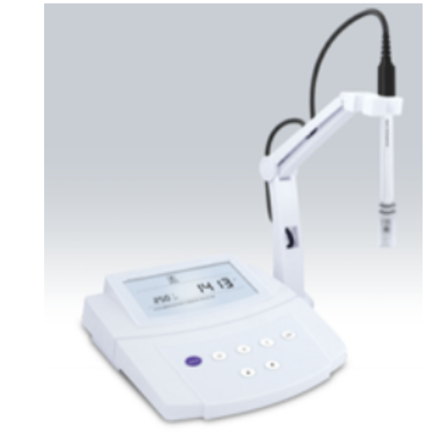
Description
Key Features
- Auto-Hold function freezes stable measured value for easy viewing and recording.
- Manual temperature calibration improves the measurement accuracy of the meter.
- Selectable temperature unit (°C or °F) meets different application requirements.
- Automatic Temperature Compensation provides accurate reading over the entire range.
- This device is suitable for routine measurements.
- 1 to 3 points push-button calibration with automatic calibration solution recognition.
- Selectable cell constant (0.1/1/10), temperature coefficient and TDS conversion factor.
- Reset feature automatically resumes all parameters back to factory default settings.
- Help message as an operational guide that helps the user quickly begin using the meter.
- System menu allows setting the 7 parameters, including the number of calibration points, temperature unit, hold function, etc.
Technical Specifications
| Conductivity | |
| Range | 0 µS/cm to 20 µS/cm
200 µS/cm 2000 µS/cm 20.00 mS/cm 200.0 mS/cm |
| Accuracy | ±1 % F.S |
| Calibration Points | 1 to 3 points |
| Calibration Solutions | 10 µS/cm, 84 µS/cm, 1413 µS/cm, 12.88 mS/cm, 111.8 mS/cm |
| Resolution | 0.01, 0.1, 1 |
| TDS | |
| Range | 0 ppt ~ 100 ppt (Max. 200 ppt, depending on factor setting) |
| Accuracy | ±1% F.S |
| TDS Factor | 0.1~1.0 (Default 0.5) |
| Temperature | |
| Range | 32 °F ~ 221 °F (0 °C~105 °C) |
| Resolution | 32.18 °F (0.1 °C) |
| Accuracy | ±33.8 °F (±1 °C) |
| Temperature Units | °C or °F |
| Calibration Range | Measured value ±50 °F (±10 °C) |
| Others | |
| Temperature Coefficient | 0.0 % to 10.0 % / °C |
| Cell Constant | K=0.1, 1, 10 or User-defined |
| Temperature Compensation | 32 ˚F ~ 212 ˚F (0 ˚C ~ 100 ˚C), Manual or Automatic |
| Reset Function | Yes |
| Hold Function | Manual or Automatic |
| Normalization Temperature | 77 ˚F (25 ˚C) |
| Power Off | Manual or Automatic (180 minutes after the last key pressed) |
| Display | LCD 5.31 in×2.95 in (135 mm×75 mm) |
| Connector | 6-pin Mini Plug |
| Power Requirements | DC 9 V, using AC adapter, 220 V AC/50 Hz |
| Dimensions | 8.26 in × 8.07 in × 2.95 in (210 mm × 205 mm × 75 mm) |
| Weight | 3.3 lbs (1.5 kg) |
Additional Information
Applications:
- Water and wastewater treatment
- Research and education
- Environmental monitoring and aquaculture
- Printing and chemical industry
ACCESSORIES:
- Conductivity Electrode
- Conductivity Calibration Solutions (84 µS/cm, 1413 µS/cm, 12.88 mS/cm)
- DC 9 V Power Adapter
- Temperature Probe

Display
This device is equipped with a clear and bright LCD display that shows measured values, mode indicators and help messages.

INDEX:
| Measurement Indicator:
Indicates meter is in the measurement mode |
|
| Calibration Mode Indicator:
Indicates meter in the calibration mode |
|
| HOLD | Hold Indicator:
Indicates the displayed value has been frozen |
| ATC | Automatic Temperature Compensation:
Indicates meter is in the temperature compensation mode |
| Setup Mode Indicator:
Indicates the meter is in SETUP mode |
Keypad
The meter has a succinct membrane keypad, names, and symbols describing the each function key controls.
| Key | Description |
| MEAS| |
· Power the meter ON/OFF.
· Freezes the measured value on the display, press the key again to resume measuring. · In the calibration or setting mode, exits current mode and returns to measurement. |
| °C | · Press the key to set the temperature or enter the temperature calibration mode. |
| MODE | · Toggles between conductivity and TDS measurement modes. |
| CAL| |
· Press the key to enter the conductivity calibration mode.
· Press and hold the key to enter the setup menu. |
| ▲ | · Press the key to increase the setting value. |
| ▼ | · Press the key to decrease the setting value. |
| ENTER | · Confirms the calibration, setting value or displayed option. |
Connectors
This conductivity meter provides 3 connectors for connecting the various types of conductivity electrodes and sensor. Listed in the below table are the details of these connectors.

| No | Connector | Function |
| 1 | COND | For connecting the conductivity electrode |
| 2 | ATC | For connecting the temperature probe |
| 3 | Power Key | For connecting the DC 9V power adapter |
Connecting the Electrode Holder
The meter comes with an easy-to-use holder for mounting the conductivity electrode and temperature probe. If necessary, please follow the steps below to install the electrode holder.
- The base of the electrode holder with an irregular round hole.

- The electrode arm has a plastic rod.

- Insert the plastic rod into the irregular round hole and swivel the electrode arm 90°. Electrode holder is now ready to swing into the desired position.

ADJUSTMENT OF ELECTRODE ARM:
After installation, if the electrode arm automatically rises or falls, you need to adjust the screws until arm locates at any position.
- Remove the plastic cover from the electrode arm.

- Use the screwdriver to tighten the screw moderately.
- Insert the plastic cover to the previous position. Installation is completed.
Connecting the Conductivity Electrode
- Take out the electrode from the packaging. Follow the steps below to place the electrode into left or right sides of the electrode arm.

- Insert the 6-pin connector into corresponding connector socket. Ensure the connector is fully seated. After the connection is completed, do not pull on the sensor cord. Always make sure that the connector is clean and dry.

Connecting the Temperature Probe
The conductivity meter comes with a temperature probe for measuring the temperature of the sample. When the probe is connected to the meter, Automatic Temperature Compensation function will immediately start.
- Place the temperature probe into the circular hole of electrode arm.

- Insert the connector of the probe into the corresponding connector socket (Marked “ATC”). Ensure the connector is fully seated.

Connecting the Power Adapter
- Before plugging in the power adapter, ensure that its voltage matches your local main voltage.
- Insert the connector of power adapter into the power socket on the meter. The meter is now ready for use.

Prior to Use
Soak the conductivity electrode for a few minutes in tap water to remove dirt and oil stains on the electrode.
Power On/Off
- Press MEAS key to turn on the meter, the display shows measured values.
- Press and hold the MEAS key for 5 seconds, the meter will turn off.
- If you do not press any key for 3 hours, the meter will turn off automatically.
Setup Menu
This meter contains an integrated setup menu that allows you to customize each displayed option to meet measurement requirements.

Setting the Default Parameters
- Press and hold the
 key for 3 seconds to enter setup menu, the meter shows selected cell constant.

- Press ▲ or ▼ key, the display successively shows 0.1, 1, 10 and USER.
- The “USER” option resembles the manual calibration function. The user only needs to input a constant value labeled on the sensor, the meter will use this value as a slope parameter to calculate measurement result.
- Once the “USER” option is enabled, the CAL key will be invalid.
- Select the cell constant according to your sensor type, press ENTER key to confirm. The meter goes to calibration point selection mode, the display shows “CAL 1”.

- Press ▲ or ▼ key to select the number of calibration points, press ENTER key to confirm. The meter goes to temperature coefficient setting mode, the display shows “COE 1%”.

- Press ▲ or ▼ key to set temperature coefficient, press ENTER key to confirm. The meter goes to TDS factor setting

- Press ▲ or ▼ key to set the TDS conversion factor, press ENTER key to confirm. The meter goes to temperature unit selection mode.

- Press ▲ or ▼ key to select the temperature unit (°C or °F), press ENTER key to confirm. The meter shows “HOLD/NO” indicating that the auto-hold function is disabled.

- If the auto-hold function is enabled, the meter will automatically sense a stable endpoint reading and freeze it. If you disable this function, the meter allows the user to freeze the reading by pressing the HOLD key.
- Press ▲ or ▼ key to enable or disable the auto-hold function, press ENTER key to confirm. The meter shows “OFF/NO” indicating that the auto-off function is disabled.

- Press ▲ or ▼ key to enable or disable the auto-off function, press ENTER key to confirm. The meter shows “RST/NO” indicating that the meter should not be reset.

- Press ▲ or ▼ key to enable or disable the reset function, press ENTER key to confirm. The meter returns to measurement mode. The setting is completed.
EXIT THE SETUP MENU:
During the setup mode, press MEAS key, the meter will return to measurement mode immediately.
Temperature Compensation
In order to get accurate measuring results, you need to enable the manual or automatic temperature compensation before measurement or calibration.
AUTOMATIC TEMPERATURE COMPENSATION
Insert the connector of the temperature probe into corresponding “ATC” socket, the display immediately shows “ATC” indicator. The meter is now switched to automatic temperature compensation mode.

MANUAL TEMPERATURE COMPENSATION:
- Do not connect the temperature probe to meter.
- Press the °C key to enter temperature setting mode.
- Press ▲ or ▼ key to set the temperature value of the sample.
- Press ENTER key to confirm, the meter returns to measurement mode. The setting is completed.
Selecting the Conductivity Electrode
The device is capable of using the three types of conductivity electrodes. Before calibration or measurement, you need to choose different sensors as per your sample concentration. The table below shows available sensor and its effective measuring ranges.
| SENSOR | MEASURING RANGES | CELL CONSTANT |
| CON- 0.1 | 0.1 µS/cm~100 µS/cm | K=0.1 |
| CON-1 | 0.01 mS/cm~10 mS/cm | K=1 |
| CON-10 | 0.1 mS/cm~200 mS/cm | K=10 |
Conductivity Calibration
Make sure that you selected the cell constant between 0.1, 1 or 10 in the setup menu. If the current option is “USER”, the automatic calibration function will be disabled.
In the automatic calibration mode, the meter allows up to 3 points calibration. To ensure higher accuracy, perform 3 points calibration or select a standard value close to the sample value you are measuring. The meter will automatically detect these conductivity standard solutions and prompt the user to calibrate the meter. When the calibration is completed, all new calibration values will automatically override existing data. The following table shows acceptable conductivity range of calibration solution for each measuring range.
| MEASURING RANGE | CALIBRATION SOLUTION RANGE | DEFAULT |
| 0 µS/cm~20 µS/cm | 7 µS/cm~17 µS/cm | 10 µS/cm |
| 20 µS/cm~200 µS/cm | 70 µS/cm~170 µS/cm | 84 µS/cm |
| 200 µS/cm~2000 µS/cm | 700 µS/cm~1700 µS/cm | 1413 µS/cm |
| 2 mS/cm~20 mS/cm | 7 mS/cm~17 mS/cm | 12.88 mS/cm |
| 20 mS/cm~200 mS/cm | 70 mS/cm~170 mS/cm | 111.8 mS/cm |
SINGLE POINT CALIBRATION:
- Rinse the conductivity electrode with distilled water, then rinse with a small amount of calibration solution.
- Press CAL key, the meter enters the calibration mode.

- Dip the electrode into the conductivity calibration solution, the display automatically shows current calibration standard (e.g., 1413µS/cm).
- Press ENTER key to confirm, the default calibration value begins flashing.

- Press ▲ or ▼ key to set each digit, press ENTER key to confirm. When the setting is completed, ensure that displayed value matches your calibration standard.
- Press ENTER key to begin the calibration. Wait for the reading to stabilize, the display will show “END”. Single point calibration is completed.

2 POINTS CALIBRATION:
- Make sure that you have selected 2 points calibration in the setup menu.
- Repeat the steps given above in the single point calibration, when the first calibration point is completed, the display will show “CAL2”. The meter prompts you to continue with second point calibration.

- Dip the electrode into the calibration solution, the display automatically shows current calibration standard (e.g., 84 mS/cm).

- Press ENTER key to confirm, the default calibration value begins flashing.
- Press ▲ or ▼ key to set each digit, press ENTER key to confirm. Wait for the reading to stabilize, the display will show “END”. Second calibration point is completed.
3 Points Calibration
- If you have selected 3 points calibration in the setup menu, the display will automatically show “CAL3”. The meter prompts you to continue with third point calibration.

- Repeat above steps until the display shows “END”, the meter returns to measurement mode. Calibration is completed.
Manual Calibration
This instrument provides a quick manual calibration mode that allows the user to easily calibrate the meter.
- Record the cell constant value on the electrode (e.g., K=1.08).

- Press and hold thekey for 3 seconds to enter the setup menu.
- Press ENTER key to confirm.
- Press ▲ or ▼ key until the display shows “USER” (User-defined) option.

- Press ENTER key to confirm, the default value begins flashing.
- Press ▲ or ▼ key to set each digit according to the previous record.
- Press ENTER key to confirm until the setting values stop flashing.
- Press MEAS key to return to measurement mode. The setting is completed.
Temperature Calibration
During the measurement, when automatic temperature compensation is enabled, if the temperature reading displayed differs from that of an accurate thermometer, you need to calibrate the meter.
- Make sure the connector of temperature probe had connected to the meter.
- Press°C key to enter the temperature calibration mode, the display shows current temperature reading.

- Press ▲ or ▼ key to set the temperature value of the sample.
- Press ENTER key to confirm. Calibration is completed.
EXIT THE CALIBRATION:
During the calibration process, press MEAS key, the meter returns to measurement mode.
Switching the Measurement Mode
- In the conductivity mode, press MODE key until the display shows “TDS”. The meter now enters to TDS measurement mode.

- Press MODE key again, the meter returns to conductivity mode.

Measurement
- Rinse the conductivity electrode thoroughly with distilled water, dip the electrode into the sample solution.
- Stir the sensor gently. Wait for the reading to stabilize, record the measured value on the display.
Hold Function
The device contains two data hold modes. When the Auto-Hold function is enabled, the meter will automatically sense a stable endpoint reading and freeze it, “HOLD” indicator appears on the display. If the Auto-Hold function is disabled, press key, the meter will immediately freeze currently displayed value. Press the key again to resume measuring.

Electrode Care and Maintenance
- Ensure that the conductivity electrode is thoroughly washed with distilled water after each use.
- If there is a build-up of solids inside the measurement area of the cell, these should be removed very carefully with a cotton bud soaked in solvent, taking care not to touch the metal parts of the inner cell.
Troubleshooting
| LCD DISPLAY | CAUSE | CORRECTIVE ACTION |
| Measured value is out of range | Check the electrode whether dirty or broken. | |
| Electrode does not suit the current sample | Replace the conductivity electrode. | |
| Setting value does not match calibration solution | Reset the calibration value. | |
| Electrode is broken | Replace the conductivity electrode. |


