Description
Overview
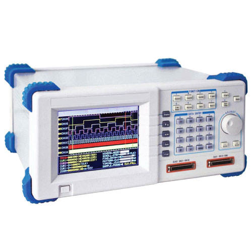
The logic analyzer is mainly used to test digital logic signal, there are 32 input channels at least and up to more 100 channels for some devices, and signal between each channel are closely related. The waveform of logic signal is the pulse waveform with different width and voltage amplitude is changeless usually, so the logic analyzer won’t concern on this part and only for the mutual time-series relationship of signal in each channel.
Features
- Large scale integrated circuit, FPGA, SOPC, high speed and large memory
- Perfect function of start, trigger, and delay to track and take the concerned data effectively.
- 32 data sampling channels, 2 external clock channels
- A fast and effective debugging tool for hardware and software of MCU
- 7″ color LCD display, the resolution 320×240 points
- USB Device and RS-232
Technical Specifications
| Input Channel | 32 data sampling channels, 2 external clock channels |
| Threshold Voltage | 6 independent and adjustable threshold voltagesAdjustable Range: -6 V to +6 V
Resolution: 0.1 V |
| Input Impedance | R ^ > 100 kΩ, C ^ < 8 pf |
| Sampling Rate | Timing Rate 1 Hz to 100 MHz (Period 10 ns to 1 s), Resolution: 10 nsState Rate 1 Hz to 35 MHz |
| Memory Depth | 256k bytes / channel |
| Trigger Condition | 32 bits trigger level, 32 bits trigger comparand |
| Event Count | 1 to 999 |
| Memory Delay | 1 to 256k sample cycles |
| Pattern Type | CH 00 to CH 15 are counters with adding 1, CH 16 to CH 29 is shift pulse CH 30 to CH 31 monitor external clk1 and clk2 |
| Pattern Rate | Frequency: 1 Hz to 50 MHz (period 20 ns to 1s)
resolution: 10 ns |
| Power | AC 100 to 240 V, 45 Hz to 65 Hz, < 30 VA |
| Display | 5.7′ TFT LCD |
| Dimension & Weight | 329 × 283 × 155 mm, approx. 9.48 lb (4.3 kg) |


