Description
Overview
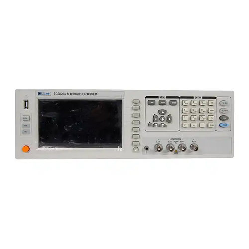
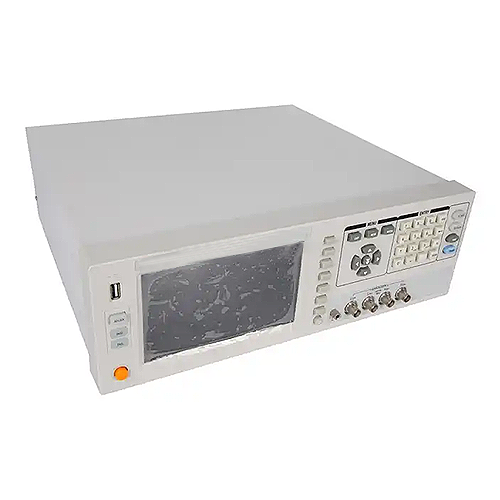
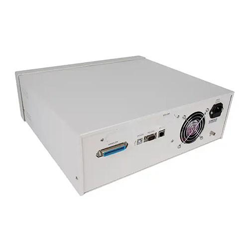
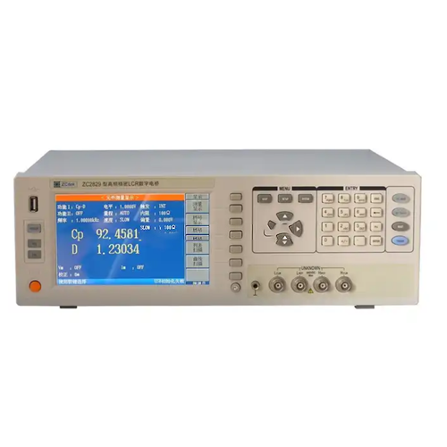
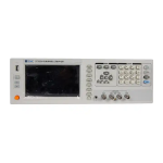
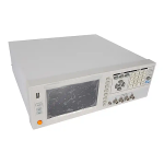
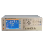
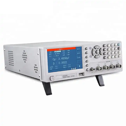
GAOTek digital precision LCR meter is a new generation impedance test instrument with high accuracy, wide measurement range, and six-digit resolution. It fulfills most low-voltage parameter measurement needs for components and materials with its basic accuracy (0.05 %), wide frequency range (from 20 Hz to 500 kHz), test signal level (5 mV to 2V), and built-in DC bias source. The instrument is widely applied in microphones, resonators, inductors, ceramic capacitors, LCD, varactor, and transformers to analyze electrical performance and test low-ESR capacitors and high-Q inductors. The HANDLER (option), GPIB (option), LAN, RS232C, and USB HOST interfaces make it easy to build an automatic component test system, communicate with the computer, and record the test results.
Features
- 800 x RGB x 480 7 in (17.78 cm) TFT LCD display
- Basic accuracy: 0.05%
- 20 Hz to 500 kHz test frequencies with 10 MHz resolution
- 10 mV to 5 V test level with a resolution of 1 mV
- 4 signal source output impedance
- 10 points list sweep function
- 20 control settings files
- 40 additional setting files can also be stored or loaded from the USB disk
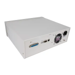
- RS232C, USB, LAN, HANDLER (option), GPIB (option) interface
- Internet connection with other instruments via LAN
Technical Specifications
|
Basic Accuracy |
LCRZ | 0.05% | ||
|
Calibration |
Warm-up time greater than 30 seconds; | |||
| Environment temperature: 73.4 °F to 41 °F (23 ºC to 5 ºC); | ||||
| Signal voltage: 0.3 VRMS to 1 VRMS | ||||
| Zeroing: After OPEN or SHORT; | ||||
| Source Impedance | 10 Ω, 30 Ω, 50 Ω, 100 Ω selectable, ±2% at 1 kHz | |||
|
AC Level |
Normal | 5 mV to 2 VRMS | Resolution: 1 mV;
Accuracy: 10% x set voltage + 2 mV |
|
| Constant level | 10 mV to 1 VRMS | |||
| DC bias voltage source (option) | 0 V to ±10 V or 0 mA to ±100 mA | |||
| LCR Parameters | Z, Y, C, L, X, B, R, G, D, Q, θ, DCR, Turn-Ratio, Phase, LK | |||
| Test parameters of LCR | 0.00001 Ω to 99.99 MΩ | |||
|
Display range of LCR parameter |
Z, R, X 0.00001 Ω to 99.99 MΩ | |||
| Y, G, B 0.00001 μs to 99.99 s | ||||
| C 0.00001 pF to 9.99 F | ||||
| L 0.00001 Μh to 99.99 Kh | ||||
| D 0.00001 to 9.99 | ||||
| Q 0.00001 to 99999.9 | ||||
| θ (DEG) -179.99 to 179.99 | ||||
| θ (RAD) -3.14 to 3.14 | ||||
| Δ% -999.99% to 999.99% | ||||
| Measurement Time (≥1 kHz) | Fast: 32 ms; Medium: 90 ms; Slow: 650 ms | |||
| Equivalent Circuit | Series; Parallel | |||
| Range Mode | Auto; Hold | |||
| Trigger Mode | Internal; Manual; External; Bus | |||
| Average Times | 1 to 255 | |||
| Calibration Function | Open, short calibration with full frequency or dot frequency, Load | |||
| Interior DC bias | 0 V, 1.5 V, 2 V; Accuracy: 1% | |||
|
Comparator |
10-bin sorting, BIN1-BIN9, NG, AUX | |||
| Bin counter | ||||
| PASS or FAIL on the front panel, LED indication | ||||
|
Memories |
20 control settings files can be stored or loaded from the internal non-volatile memory | |||
| 40 additional setting files can also be stored or loaded from the USB disk | ||||
|
Interface |
Control | HANDLER (option) | ||
| Communication | LAN, GPIB (option), RS232C | |||
| Memory | USB HOST | |||

