Description
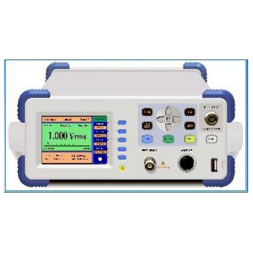
GAOTek Digital RF Millivoltmeter and Frequency Counter is a new type of micro-controller digital intelligent instruments. It can measure the sinusoidal signal voltage from 9 kHz ~ 3000 MHz . The instrument uses a QVGA color LCD display with clear reading and has long life. The machine has a good frequency response, small standing wave co-efficient, high sensitivity, low power consumption, small size and is light weight. With RS-232 interface and optional GPIB interface and USB interface, can be remote measurement control. But also and computer and other equipment composed of automated test system, is the workshop production and the laboratory UHF voltage measurement of the necessary equipment.
Features
- A new microprocessor chip with high resolution, high precision, cost-effective and other outstanding advantages
- Special QVGA color LCD display, conductive key function control, clear reading, easy to operate
- SMT production process, the new metal chassis
- High reliability: > 20000 h
- Standard RS232 interface, optional GPIB and USB interface
- Rapid frequency response
- Small standing wave coefficient
- High sensitivity, accuracy and reliability
- High price-to-quality ratio
- Light weight and compact
- Low power consumption
Technical Specifications
| Frequency Range of Voltage to Be Measured | 1.2 GHz RF Probe: 9 kHz to 1200 MHz | ||||
| 2 G Coaxial Detector: 10 kHz to 2000 MHz | |||||
| 3 G Coaxial Detector: 10 kHz to 3000 MHz | |||||
| Voltage Measurement Range | 1 mVrms to 10 Vrms, 50 Ω | ||||
| Level Measurement Range | -47 dBm to 33 dBm, 50 Ω | ||||
| Voltage Ranging | 4 mVrms/40 mVrms/400 mVrms/4 Vrms/10 Vrms | ||||
| Level Ranging | -40/-20/0/20/40 dBm | ||||
| Coaxial Detector Frequency Response Error | Frequency Range | 2 GHz Coaxial Detector | 3 GHz Coaxial Detector | ||
| Ranging | 2.25 V to 10 mVrms (20 dBm to -27 dBm) | 10 mV to 2 mVrms (-27 dBm to -41 dBm) | 2.25 V to 10 mVrms (20 dBm to -27dBm) | 10 mV to 2 mVrms (-27 dBm to -41 dBm) | |
| 100 kHz to 100 MHz | ± 2% | ± 3% | ± 2% | ± 3% | |
| 10 kHz to 200 MHz | ± 3% | ± 4% | ± 3% | ± 4% | |
| 200 MHz to 600 MHz | ± 5% | ± 7% | ± 5 % | ± 7 % | |
| 600 MHz to 1000 MHz | ± 8% | ± 9% | ± 7% | ± 9% | |
| 1000 MHz to 1500 MHz | ± 12% | ± 13% | ± 12% | ± 13% | |
| 1500 MHz to 2000 MHz | ± 15% | ± 16% | ± 16% | ± 17% | |
| 2000 MHz to 2500 MHz | − | − | ± 15% | ± 16% | |
| 2500 MHz to 3000 MHz | − | − | ± 17% | ± 18% | |
| Surface SW Coefficient of 10 V Coaxial Detector (50 Ω) | Frequency Range | SW Coefficient | |||
| 10 kHz to 200 MHz | ≤ 1.03 | ||||
| 200 MHz to 500 MHz | ≤ 1.04 | ||||
| 500 MHz to 1000 MHz | ≤ 1.15 | ||||
| 1000 MHz to 1600 MHz | ≤ 1.25 | ||||
| 1600 MHz to 2000 MHz | ≤ 1.35 | ||||
| 2000 MHz to 3000 MHz | ≤ 1.40 | ||||
| Reference Output | Output Voltage:1 VRMS | ||||
| Output Frequency:about 100 kHz | |||||
| Output Impedance:50 Ω | |||||
| Frequency Counter (configurable) | Frequency Range | 10 kHz to 1 GHz/2.5 GHz/3 GHz | |||
| Input Characteristics | Minimum input voltage: 50 mV | Maximum input voltage: 50 mV | Time base: 10 MHz Stability 5×10⁻⁶ | ||
| Dimensions | 10.03 in x 14.56 in x 3.93 in (255 mm × 370 mm × 100 mm) | ||||
| Weight | 7.71 lbs (3.5 kg) | ||||
Additional Information
Rear Panel Description

1)Power Supply Socket
2)GPIB Connector (optional)
3)RS232 connector (standard)
4)USB connector(optional)
Preparations before Operation
1.1.1 Check before the Operation
First, carefully check the mains voltage to ensure that it meets the operation voltage range of this instrument before plugging the power cord into the power socket on the rear panel. Carefully check the power supply of the test system to ensure good grounding. The cabinet of the instrument and all the exposed metal should be well grounded. No potential difference exists between all the instruments linked. In voltage measurement, push the aero-socket of the voltage input channel into the aero-connector of the voltage measurement device.
1.1.2 Turning on the Instrument
When turning on the instrument, break the input signal at the coaxial detector to ensure normal initialization of the instrument.
Press the power switch on the front panel and the instrument begins initialization. The model number of the instrument will be displayed after VFD screen and LED lamps are lighted. After initialization, the LED lamps of voltage input channel and auto-ranging will be on.
1.2 Measurement in Voltage Input Channel
1.2.1 General
The voltage of the signal applied to voltage input channel is to be measured.
If the signal to be measured is the signal in voltage input channel, the “voltage channel indication lamp” will be lighted. Otherwise, press【VOLT】key to select the voltage input channel signal as the signal to be measured; and the “voltage channel indication lamp” will be on.
1.2.2 Zeroing
Zeroing for the instrument is necessary before measurement begins, so as to ensure the accuracy in the measurement made for voltage below 20mVrms.
When zeroing, the signal at the input terminal of the detector must be removed. Press 【SHIFT】key before 【MIN】key; and “ZEROING” will be displayed on the screen. When zeroing is finished, the voltage value after zeroing will be displayed. Zeroing is impossible if there is signal at the input terminal of the detector. This signal must be removed.
Note: In measurement of small signal below 4 mVrms, it’s better to do it in a shielded room so as to ensure measurement accuracy for small signal.
1.2.3 Range Selection
Either automatic range or manual range can be selected in voltage input channel.
Five ranges are available in this instrument:
|
Name of Range |
Voltage Scope |
Display Form of RMS |
|
4mVrms |
0 mVrms~ 4.0mVrms |
3.000 mVrms |
|
40mVrms |
3.6mV rms~ 40mVrms |
30.00 mVrms |
|
400mVrms |
36mVrms ~ 400mVrms |
300.0 mVrms |
|
4Vrms |
360mV rms~ 4.0Vrms |
3.000 Vrms |
|
10Vrms |
3.6V rms~ 10Vrms |
5.00 Vrms |
The range of the instrument can be determined by the position of the decimal point and unit of the RMS display form. Usually automatic ranging is used in for accurate measurement.
When manual ranging is used, if the input voltage is higher than the upper limit of the selected range, more error will be resulted in the measured data.
1.2.3.1 Auto Ranging
Press (AUTO) key to enter into an automatic ranging mode; and the auto-ranging indication lamp will be lighted.
In auto-ranging, the instrument will automatically change the range according to the current voltage value. If the current voltage value is bigger than the upper limit of the current range, it will be increased to above range. If the current voltage value is smaller than the lower limit of the current range, it will decrease to the next range.
1.2.3.2 Manual Ranging
Press【▲】and【▼】keys to enter into manual ranging mode. The auto ranging indication lamp will be off. Press 【▲】key to decrease the current range for one step. Press【▼】key to increase current range for one step.
In manual ranging, the range can be set as required. If the input voltage is higher than the upper limit of the current selected range of 275 %, input overload“OVLD” will be displayed; but the decimal point and unit will not change. For example, the current selected range is 400 mVrms range. If the input voltage is higher than 1100.0mVrms, overload symbol “OVLD mVrms” will be displayed; the decimal point and unit keep identical with 400mVrms range. When the overload is displayed, one range should be increased so as not to damage the instrument.
Resolution and measurement speed can be raised in manual ranging. But if the input voltage is higher than the upper limit of the current range, more error will be resulted.
Note:Manual ranging is not available in power measurement.
1.2.4 Display Unit
There are two kinds of unit displayed for voltage input channel: one is dB and dBm, the
another is mVrms and Vrms.
Press【dBm/V】key to switch the unit displayed.
If the present displayed unit is dB or dBm, by pressing 【dBm/V】key, the displayed unit will be changed to mVrms or Vrms; if the present unit displayed is mVrms or Vrms, it will be changed to dB or dBm by pressing again 【dBm/V】key.
1.2.5 Measurement Rate
Press【FAST】key, to select “fast” measurement; while press 【SLOW】key to select “slow” measurement. Measurement rate includes “fast” and “slow”.
The measured rate of “slow” is 2 times per second, displaying 4 effective digits. The measured rate of “fast” is 20 times per second, displaying 3 effective digits; the last digit displayed “o” remains unchanged.
1.2.6 Calculation Function
This instrument can calculate “max. value”, “min. value” and “relative value”. Three indication lamps “MAX”, “MIN” and “REL” are used to indicate which calculation function is enabled at that time. If the three lamps are all off, the calculation function is shut off and the instrument is in basic measurement function. The present displayed voltage value is the real measured value.
1.2.6.1 Basic Measurement Value
When the three indication lamps “MAX”, “MIN” and “REL” are all off, the instrument is in the basic measurement mode. The displayed value at that time is the real measured value.
1.2.6.2 Maximum and Minimum Values
If the instrument is neither in maximum value nor in minimum value function, and keys (MAX) or (MIN) is pressed, respectively to enter into maximum or minimum value calculation function, it begins to calculate the maximum and minimum values of the measured voltage. This time is called start time of maximum and minimum values. That is, the calculation of maximum and minimum values starts simultaneously.
After calculation of maximum and minimum values of measured voltage begins, press 【MAX】key in minimum value function, you may view the maximum value of measured voltage beginning from start time; press 【MIN】key in the maximum value function, you may view the minimum value of measured voltage beginning from start time. This will not change the start time for re-setting the maximum and minimum values.
If you want to reset, i.e., re-calculate the start time of maximum and minimum values, you must first quit maximum and minimum values function then re-enter maximum or minimum value function.
When the instrument is in maximum value function, press【MAX】 key to quit maximum value function and enter into basic measurement function. The maximum value indication lamp will be off and the real measured voltage will be displayed on the screen.
When the instrument is in maximum value function, press【MIN】 key to quit minimum value function and enter into basic measurement function. The minimum value indication lamp will be off and the real measured voltage will be displayed on the screen.
1.2.6.3 Relative Value
1.2.6.3.1 If the instrument is not in the relative value function, press【REL】key to set the present measured voltage value as reference and enter into relative calculation function. If the present displayed unit is dBm, the set reference will be a dBm reference value. And if the present displayed unit is RMS, the set reference will be an RMS reference value. In relative value calculation, if【dBm/V】key is pressed for conversion of unit, dBm and rms reference values will be converted according to the following equation:
dBm reference value = 10lg (rms reference value)
Relative value = present measured voltage value – reference value
1.2.6.3.2 If the instrument is in relative function at present, press【REL】 key to enter into basic measurement function, and the relative value indication lamp is off.
1.2.6.3.3 RMS Relative Value and dB Relative Value
Relative values are divided into rms relative value and dB relative value, which are converted by 【dBm/V】key.
The RMS relative value function is also called NULL function. dB relative value function is also called dB function.
RMS relative value = rms value of present measured voltage – rms reference value
RMS reference value is also called OFFSET value of NULL function.
dB relative value = dBm value of present measured voltage – dBm reference value
dBm reference value is also called REFERENCE value of dB function.


