


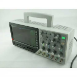

GAOTek Waveform Oscilloscope
This Waveform Oscilloscope has 0 V to 3 V input voltage range, 8 channels, 1 M sample depth, 200 K maximum input impedance, and 7 in display.
Description
Description
Features
- 8 Channel Logic Analyzer
- 7 in (17.78 cm) WVGA Display: 64 K Color, 800 x 480 resolution
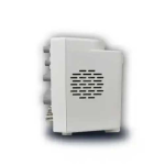
- Ultra-Thin, Portable Design for On-the-Go Use
- 500 MHz Sample Rate
- 1 M Record Length
Technical Specifications
| Channels | 4 |
| Bandwidth | 70 MHz |
| Rise Time | 5 ns |
| Real Time Sample Rate | 1 GSa or s |
| Record Length | 1 M |
| SEC Or DIV Range | 4 ns or div to 40 s or div |
| Delay Time Accuracy | 500 PS |
| A or D Converter | 8 bits resolution |
| Volts Or Div Range | 2 mV or div to 5V or div at input BNC |
| Position Range | 20 ns or div to 80 us or div (-8 divx s or div) to 40 ms, 200 us or div to 40 s or div, (-8 divx s or div) to 4005, |
| DC Gain Accuracy | ±3% for Normal or Average acquisition mode, 5 V or div to 10 mV or div ±4% for Normal or Average acquisition mode, 5mV or div to 2mV or div |
| Inputs Coupling | AC, DC, GND |
| Input Impendence | 1 MO +2%, 20 pF + 3 pF |
| Probe Attenuation | 1 X, 10 X |
| Trigger System | |
| Trigger Types | Edge, Video, Pulse, Slope, Over time, Alternative |
| Trigger Source | CH 1, CH 2, EXT, EXT/5, AC Line |
| Trigger Modes | Auto, Normal, Single |
| Coupling Type | DC, AC, Noise Reject HF Reject, LF Reject |
| Trigger Sensitivity
(Edge Trigger Type) |
DC (CH 1, CH 2 CH 3, CH 4): 1 div from DC to 10 MHz; 1.5 div from 10 MHz to Full; DC (EXT): 200 mV from DC to Full; DC (EXT or 5):1 1 V from DC to Full; AC: Attenuates signals below 10 Hz HF Reject Attenuates signals above 80 kHz; LF Reject Same as the DC-coupled limits for frequencies above 150 kHz attenuates signals below 150 Hz |
| Trigger Level Range | CH 1. CH 2 CH 3, CH 4: 8 divisions from centre of screen EXT: 1.2 V EXT or 5: 6 V |
| Trigger Level Accuracy (Typical) Signals Having Rise
And Fall Times >20 ns Set Level To 50% (Typical) |
CH 1, CH 2, CH 3, CH 4: 0.2 div x volts div within +4 divisions from centre of screen; |
| EXT + (6% of setting +40 mV) | |
| EXT or 5: x (6% of setting +200 mV); | |
| Operates with input signals >50 Hz | |
| Measurement | Manual Voltage difference between cursors AVs |
| Cursor Measurement | Time difference between cursors: AT |
| Reciprocal of AT in Hertz (1 or AT) | |
| Tracing The voltage and time at a waveform point | |
| Frequency Period Mean, Pk-Pk, Cyclic RMS, Minimum, Maximum, Rise time, Fall Time, +Pulse | |
| Auto Measurement | Width, -Pulse cluty, -Duty, Vbase, Vtop. Vmid, Vamp. Overshoot |
| Preshoot BWIDTH FRF | |
| Logic Analyzer Specifications | |
| Channels | 8 Channels |
| Max Input Impendence | 200 K (C= 10 p) |
| Input Voltage Range | 0 V to 3 V |
| Logic Threshold Range | 0 V to 3 V |
| Max Sample Rate | 500 MSa or s |
| Compatible Input | TTL CMOS, ECL |
| Sample Depth | 1 M |