Description
Overview
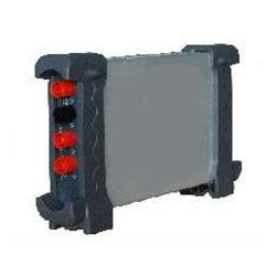
The GAOTek High Performance Bluetooth/USB Wireless Data Logger is specially designed for long time recording of voltage, current, resistance, continuity and capacitance and is able to create trend curves in real time. It features safe electrical isolation, true RMS measurement, plug and play USB interface, bluetooth wireless transmission and flexible control software. The compact wireless data logger can be used with mobile phones and tablets using the Android system and also runs under Windows 7, Windows 2000 and Windows XP operating systems.
Key Features
- Long time record voltage, current, resistance, capacitance and on-off etc. in real time, and create trend curves.
- Plug play USB interface.
- Simple, handy and flexible control software.
- Software support: Windows 2000, Windows 7, Windows XP, Win8.
Technical Specifications
| Function | Range | Accuracy | Resolution |
| DC Voltage | 60.00 mV | ±1 % ±1 digit | 10 uV |
| 600.00 mV | 100 uV | ||
| 6.00 V | 1 mV | ||
| 60.00 V | 10 mV | ||
| 60.00 V | 100 mV | ||
| 800 V | 1 V | ||
| AC Voltage | 60.00 mV | ±1 % ±3 digit | 10 uV |
| 600.00 mV | 100 uV | ||
| 6.00 V | 1 mV | ||
| 60.00 V | 10 mV | ||
| 600.0 V | 100 mV | ||
| DC Current | 60.00 mA | ±1.5 % ±1 digit | 10 uA |
| 600.00 mA | ±1 % ±1 digit | 100 uA | |
| 6.000 A | ±1.5 % ±3 digit | 1 mA | |
| 10.00 A | 10 mA | ||
| AC Current | 60.00 mA | ±1.5 % ±1 digit | 10 uA |
| 600.00 mA | ±1 % ±1 digit | 100 uA | |
| 6.000 A | ±1.5 % ±3 digit | 1 mA | |
| 10.00 A | 10 mA | ||
| Resistance | 600 | ±1 % ±3 digit | 0.1 Ω |
| 6.000 K | ±1 % ±1 digit | 1 Ω | |
| 60.00 K | 10 Ω | ||
| 600.0 K | 100 Ω | ||
| 6.000 M | 1 KΩ | ||
| 60.00 M | ±1.5 % ±3 digit | 10 KΩ | |
| Capacitance | 40.00 nF | ±1 % ±1 digit | 10 pF |
| 400.00 nF | 100 pF | ||
| 4.000 uF | 1n F | ||
| 40.00 uF | 10 pF | ||
| 400.0 uF | 100 pF | ||
| Attention: The smallest capacitance value that can be measured in 5 nF | |||
| Diode | 0 V~2.0 V | ||
Additional Information
1.The User interface
Click the software icon on the desk after you finished the software setting and equipment connecting. Then a user interface will be showed as follows:

Description:
- Data List
- Description
DC: DC voltage/DC current measurement
AC: AC voltage/AC current measurement
![]() : Diode measurement
: Diode measurement
![]() : On-Off test
: On-Off test
![]() : Capacitance measurement
: Capacitance measurement
- Manual/Auto: Select manual or auto measurement type.
- Measured valu
- Trend chart
- Voltage button
- Current button
- Resistance button
- Diode button
- On-Off test
- Capacitance button
- Temperature measurement
- DC: click DC to switch to AC.
- Auto: Click Auto to switch to manual mode
- Relative Measurement
- Stop/Run: Stop or start acquire data
- Help menu
- Data Interval: 1 s~100 s
- Save data
- Clear data list
2.Install Software
Caution: You must install the software before using the Data Logger.
- While in Windows, insert the installation CD into the CD-ROM drive.
- The installation should start up automatically. Otherwise in Windows Explorer, switch to the CD-ROM drive and run Setup.exe.

3. The software installation is started. Click ‘Next’ to continue.
4. Choose a Setup Type directory. Click ‘Next’ to continue.
5. Check the setup information. Click Next to start copying of Files.
6. Updating System Configuration
7. The installation is complete.
3. Install Driver
1. Connect the A-Type Plug of USB cable to your PC’S USB port.

2. Connect the B-Type Plug of USB cable to USB port.

3. New hardware is found.
4. New hardware search wizard starts.
5. New hardware search wizard starts to search the driver.
6. New hardware wizard installs “DRIVER”.

7. The wizard has finished installing for “DRIVER”.
4. Connect to Bluetooth
- Insert the bluetooth dongle to PC USB port. After waiting for several seconds, install the bluetooth driver automatically. Open the computer control panel, you will see the bluetooth icon on the lower right corner of the computer.
![]()
2. Press the switch, and the red light will be on.
Double-click the bluetooth icon on the lower right corner of the computer, and click “Add a device”.
3. Next, and input the pairing code “1234”, the device will be successfully added to the computer.

- Right click application icon to look up for properties. On the hardware bar you will check and remember the COM port number what the blue-tooth device uses.
- Run “USB”, there will have a prompt “No usb device was found”, and please click “OK”. Now please click “Stop”, and select connection mode to “RS-232”. Set Port to the COM port number. Then click “open”, the software will work normally.
![]()
5. Operating Data Logger
5.1 Making Voltage Measurement
1. Making a DC Voltage Measurement
To measure a DC voltage, follow these steps:
- Click the “V” key and DC appears at the top of the screen.
- Connect the black lead into the COM banana jack input and the red lead into the V/Ω/C banana jack input.
- Connect the red and black leads to the measured points and the voltage value of measured points is displayed on the screen.
Connect Data Logger probes as illustrated in the following figure:

Figure 2-1
Then, the following figure will be displayed:

Figure 2-2 DC Voltage Measurement
![]() : Save data as .txt.
: Save data as .txt.
![]() : Clear the right data list.
: Clear the right data list.
![]() : Start to acquire data.
: Start to acquire data.
![]() : Get users’ help.
: Get users’ help.
![]() : Set data interval 1s, 2s, 5s, 10s.
: Set data interval 1s, 2s, 5s, 10s.
2. Making an AC Voltage Measurement
To measure the AC voltage, follow these steps:
- Click the “V” key and DC appears on the screen.
- Click “DC” key and AC appears on the screen.
- Connect the black lead into the COM banana jack input and the red lead into the V/Ω/C banana jack input.
- Connect the red and black leads to the measured points and the AC voltage value of measured points will be displayed on the screen.
Connect Data Logger probes as illustrated in the following figure:

Figure 2-3
Then, the following figure will be displayed:

Figure 2-4 AC Voltage Measurement
The user can select Auto measure and Manual measure. Voltage range can be set 60.00 mV, 600.0 mV, 6.000 V, 60.00 V, 600.0 V.
5.2 Making Current Measurement
1. Making a DC Current Measurement
To measure a DC current which is less than 600 mA, follow these steps:
- Click the “A” key and then “DC” appears on the screen. The unit on the main reading screen is “mA”. Click “A” key to switch the measurement between mA and A. The default is 600 mA. Click “Auto” key to switch the measurement range from 60 mA to 600 mA.
- Connect the black lead into the COM banana jack input and the red lead into the mA banana jack input.
- Connect the red and black leads to the measured points and the DC current value of measured points will be displayed on the screen.
Connect Data Logger probes as illustrated in the following figure:

Figure 2-5
Then, the following figure will be displayed on the screen:

Figure 2-6 DC current Measurement for 600 mA
To measure a DC current which is larger than 600 mA, follow these steps:
- Click the “A” key and then “DC” appears on the screen. The unit on the main reading screen is mA.
- Click “A” key to switch to 10 A measurement, the unit on the main reading screen is A.
- Connect the black lead into the COM banana jack input and the red lead into the 10 A banana jack input.
- Connect the red and black leads to the measured points and the DC current value of the measured points will be displayed on the screen.
- Click “A” to return to 600 mA measurement.
Connect Data Logger probes as illustrated in the following figure:

Figure 2-7
Then, the following figure will be displayed on the screen:

Figure 2-8 DC current Measurement for 10 A
2. Making an AC Current Measurement
To measure an AC current which is less than 600 mA, follow these steps:
1) Click the “A” key and then “DC” appears on the screen. The unit on the main reading screen is “mA”, and “mA” will display on the screen, Click “mA” to switch the measurement between mA and the default is 600 mA.
- Click “DC” key and AC will display on the screen.
- Connect the black lead into the COM banana jack input and the red lead into the mA banana jack input.
- Connect the red and black leads to the measured points and the AC current value of measured points will be displayed on the screen.
Connect Data Logger probes as illustrated in the following figure:

Figure 2-9
Then, the following figure will be displayed on the screen:

Figure 2-10 AC current Measurement for 600 mA
To measure an AC current which is larger than 600 mA, follow these steps:
- Click the “A” key and then “DC” appears on the screen. The unit on the main reading screen is mA.
- Click the “DC” key and then “AC” appears on the screen.
- Click “mA” key to switch to 10 A measurement, the unit on the main reading screen is A.
- Insert the black lead into the COM banana jack input and the red lead into the 10 A banana jack input.
- Connect the red and black leads to the measured points and the AC current value of the measure points will be displayed on the screen 6) Click “A” to return to 600 mA measurement.
Connect Data Logger probes as illustrated in the following figure:

Figure 2-11
Then, the following figure will be displayed on the screen:

Figure 2-12 AC current Measurement for 10 A
5.3 Measuring Resistance Values
To measure a resistance, follow these steps:
- Click the “OHM” key and then resistance measurement window appears on the screen.
- Connect the black lead into the COM banana jack input and the red lead into the V/Ω/C banana jack input.
- Connect the red and black test leads to the resistor. The resistance value is shown on the screen in Ohm.
Connect Data Logger probes as illustrated in the following figure:

Figure 2-13
Then, the following figure will be displayed on the screen:

Figure 2-14 Resistance Measurement
5.4 Making a Diode Measurement
To make a measurement on the diode, follow these steps:
- Click the “Diode” key and a diode symbol appears at the top of the screen.
- Connect the black lead into the COM banana jack input and the red lead into the V/Ω/C banana jack input.
- Connect the red and black leads to the diode and the voltage value of the diode is displayed on the screen in volt.
Connect Data Logger probes as illustrated in the following figure:

Figure 2-15
Then, the following figure will be displayed on the screen:

Figure 2-16 Diode Measurement
To perform an On-Off test, follow these steps:
- Click the “CONTI” key and then On-Off indictor appears on the top of the screen.
- Connect the black lead into the COM banana jack input and the red lead into the V/Ω/C banana jack input.
- Connect the red and black leads to the tested points. If the resistance value of the test points is less than 10 Ω, you will hear beep sound from the test tool.
Connect Data Logger probes as illustrated in the following figure:

Figure 2-17
Then, the following figure will be displayed on the screen.

Figure 2-18 On-Off Measurement
5.5 Making a Capacitance Measurement
To measure a capacitance, follow these steps:
- Click the “CAP” key and a capacitor symbol appears on the top of the screen
- Connect the black lead into the COM banana jack input and the red lead into the V/Ω/C banana jack input.
- Connect the red and black leads to the capacitor and the capacitance value is displayed on the screen in μF or nF.
Connect Data Logger probes as illustrated in the following figure:

Figure 2-19
Then, the following figure will be displayed on the screen.

Figure 2-20 Capacitance Measurement
5.6 Selecting Automatic/Manual Range Adjustment
The default range mode of the instrument is automatic range. If you are using the DC/AC mode, to switch to the manual range, do these steps:
- Click “Auto” key to enter the manual range mode and then Manual is displayed on the top of the screen.
- Under the manual range mode, the measuring range is increased by a stage, Click “Auto” to switch manual.
- Click “Manual” key to switch back to the automatic range mode and then Auto is displayed on the top of the screen.
Attention: capacitance measurement without manual range mode.
5.7 Taking a Relative Measurement
A currently measured result relative to the defined reference value is displayed in a relative measurement.
The following example shows how to take a relative measurement. At first, it is required to acquire a reference value.
- Click the V/A/OHM/CAP key.
- Connect the black lead into the COM banana jack input and the red lead into the V//Ω/C banana jack input.
- Connect the red and black test leads to the tested device. The value is shown on the screen.
- Click
 key then
 is displayed on the top of the screen. The saved reference value is displayed beside.
Then, the following figure will be displayed on the screen.

Figure 2-21 Relative Measurement
5.8 Temperature Measurement
The series of Bluetooth/USB Data Logger can measure temperature.
- Click the T key.
- Connect the black lead into the mA banana jack input and the red lead into the V//Ω/C banana jack input.
- Connect the red and black test leads to the tested device. The value is shown on the screen.

Figure 2-22
Connect the thermocouple sensor of the metal parts with the tested device. Then, the following figure will be displayed on the screen.

Figure 2-23 Temperature Measurement
Click C key to switch to Fahrenheit. And Click F key to switch to Celsius.
Specifications:
Data Logger Mode
| Maximum Resolution | 6000 Counts | |
| DMM Testing Modes | Voltage, Current, Resistance, Capacitance, Diode & | |
| Continuity | ||
| Maximum Input Voltage | AC: 600 V DC: 800 V | |
| Maximum Input Current | AC: 10 A DC: 10 A | |
| Input Impedance | 10 MΩ | |
Standard accessories
- Data Logger Probes x 2
- A USB Cable
- A PC software CD of the Data Logger
- A Thermocouple Sensor
Optional accessory
Bluetooth adapter


