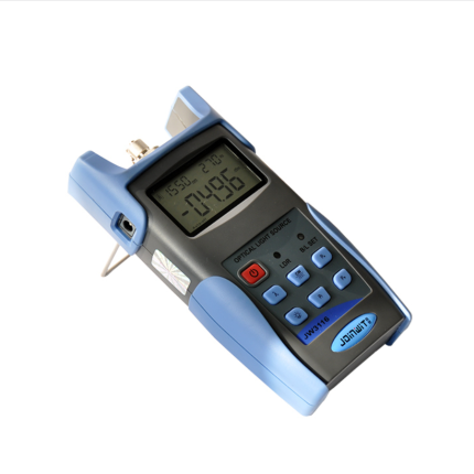
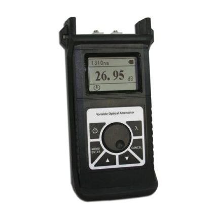
Description
Key Features
- Wide power measurement range
- Power measurements in dBm or mw and Insertion loss in dB
- Self-calibration function
- Maximum continual operation of 240 Hours
- Optional auto-off function
- Comfortable LCD display
Technical Specifications
| Type | GAO-OPM-113-A | GAO-OPM-113-B |
| Wavelength | 800 nm to 1700 nm | |
| Detector | InGaAs | |
| Measurement Range | -70 dBm to 3 dBm | -50 dBm to 26 dBm |
| Uncertainty | ± 5% | |
| Calibrated Wavelength | 850 nm, 980 nm, 1300 nm, 1310 nm, 1490 nm, and 1550 nm | |
| Resolution | 0.01 dB | |
| Optical Connector | FC (interchangeable SC, ST) /as well as 0.09 in (2.5 mm) universal | |
| Power Supply | Alkaline battery (3 AA 1.5 V batteries) | |
| Battery Operating Time | 240 h with 1.5 V battery(3) | |
| Operating Temperature | (14 °F to 140 °F) -10 °C to 60 °C | |
| Storage Temperature | (-13 °F to 158 °F )-25 °C to 70 °C | |
| Relative Humidity | 0 to 95% (non-condensing) | |
| Dimension | 5.98 in x 2.91 in x 1.02 in (152 mm x 74 mm x 26 mm) | |
| Weight | 7.05 oz (200 g) | |
- Component Guide
a. LCD
The LCD screen displays the measurement tested in dB, dBm, mW, uW, nW unit, the selected wavelength, the current operating mode and so on.
b. ON/OFF Key
Press the key to turn the unit on/off.
c. dB Key
Tests the power value under certain wavelength
d. ZERO Key:
Press the key for auto-zero.
e. “λ” Key:
To switch to the current operating wavelength between 850 nm, 980 nm, 1300 nm, 1490 nm and 1550 nm.
f. LIGHT Key:
To turn the background light on/off .
2. Operation and Notes
- ON/OFF
- Press the On/Off key for a few seconds to turn on the unit
- Press the On/Off key for a few seconds to turn off the unit
- Absolute power measurement
- Turn on the Power Meter
- Press the λ key to switch between the wavelengths. The default wavelength is 1310nm
- Connect the light to be measured and then the reading will be displayed on the LCD screen, including Linear and nonlinear value.
- Relative power measurement.
- Select the wavelength to be measured.
- Under “Absolute power measurement mode”, connect to the light to be tested
- Press dB key, then current power value is stored as a reference value in dB unit. At the same time it also displays the current absolute power value and current relative value as 0 dB
- Connect to another beam of light to be tested, displays the current relative power value and absolute power value under test.
- Special function
It has 3 kinds of working mode:
(1) Factory Mode
(2) User Mode
(3) Working Mode
Factory Mode: The factory mode is responsible for the test and calibration
User Mode: Press the λ + Light key synchronously to enter the User mode. Numeral “1” will be displayed on the top right corner. Press the λ + Light key synchronously once again to exit from the User mode and enter the Working mode. Numeral “0” will be displayed on the top right corner.
| Function | Button | ――― |
| Plus 0.05 | Light | ――― |
| Minus 0.05 | dB | ――― |
| Store | Zero | ――― |
| Switch Wavelength | λ | ――― |
| Return to the Factory Setting | λ+ Zero | ――― |
Notes: If any errors or mistakes are caused by the user self-calibration operation, please press the λ+ Zero synchronously under the user mode to go back to the factory setting.
- Auto-off:
Press LIGHT + dB key to turn on the auto-off function. The auto-off symbol will be displayed on the top right. The unit will be turned off automatically after 10 minutes idle time.
- Background light On/Off:
Under the Working Mode, press LIGHT to turn the background light On/Off. A little sun symbol will be displayed on the top right.
Appendix:
Optical fiber loss measurement
Step 1- Optical Reference Level
- Turn on optical power meter and press the λ key to select the wavelength.
- Turn on optical light source (emitting source) and select the wavelength. Wait for 1-2 minutes until it stabilizes
- Select a piece of patch cords which is used to connect with the light source; we call it emitting patch cords. Clean the connector of the patch cords. The fiber of the emitting source patch cords must be the same fiber type as the fiber under test
- Connect the light source (emitting source) with the Handheld Power Meter through the emitting source patch cords
- Handheld Power Meter gets the power measurement value. This value should be close to the one to the light source (emitting source) that is set. If it has wide disparity, please make sure the fiber connection is cleaned properly else replace with other jumpers
- Press the dB key; the reading 0.00dB will be displayed on the screen. The tested power values will be set to the reference value.
Step 2-Optical Loss Measurement
- Keep the emitting source patch cords connected with the light source (emitting source)
- Connect the Handheld Power Meter and light source (emitting source) to the optical fiber link respectively.
Notes: Cleaning the connector’s surface including all the necessary optical adaptors. The reading in dB unit displayed on the screen is the tested optical fiber link loss (also display the current absolute optical power value in dBm unit)
3. Maintenance
- It is important to keep all optical connectors and surfaces free from oil, dirt or other contaminated substances to ensure proper operation
- Use one type of adapter to avoid excess loss from different connectors
- Please use dust proof cap for protection to avoid any scratches or contamination when Handheld Power Meter is not in operation
- Light interface is sensitive, please carefully plug in and pull out the connectors
- Please use clean cotton to clean the sensor surface. Clean it in clockwise direction carefully.
- If it is not used for a long time, please take out the battery.
4. Troubleshooting
| Description | Problem | Method |
| Faint LCD display | Battery is weak | Change battery |
| No display after turning on the unit | Battery is weak/Others | Turn on the unit again/Change battery |
| Insensitive display in LCD | Light interface is polluted/ broken/Display locked | Check connector carefully and clean sensor’s interface |
5. Change Battery
If you find that the battery is weak while operating it, please immediately turn the unit off and change to new battery.
Applications:
- Absolute power measurements in fiber optic signals
- Measurement of optic loss in fibers
- Detection of optical test tones
- Maintenance and construction of fiber communication and CATV systems
Ordering Information
| GAO-OPM-113-A | GAO-OPM-113-B | |
| Measurement Range | -70 dBm to 3 dBm | -50 dBm to 26 dBm |
| Other Accessories | Optical Power Meter, Protective Rubber Boot, 3 pieces 1.5 V batteries, User Manual, Cotton Swabs and Soft carrying case | |


