Description
Overview
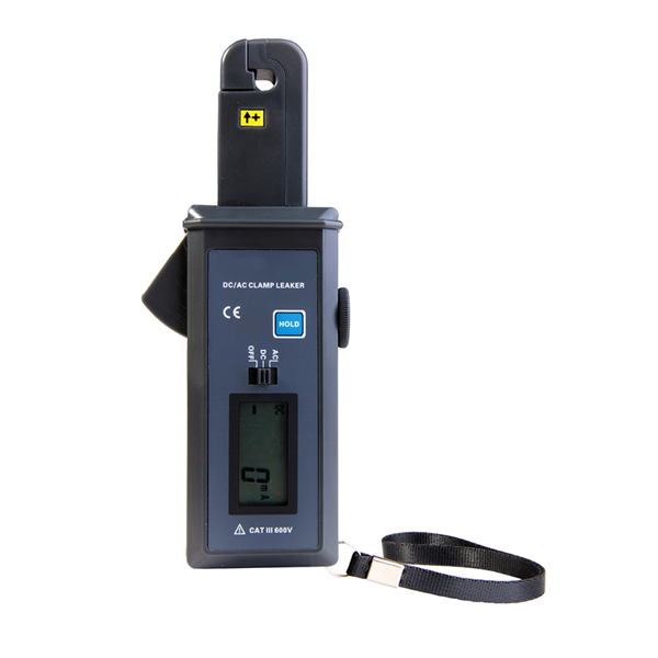
The GAOTek AC and DC Clamp Meter with Integral Test is specially designed for measuring AC/DC current and leakage current with modern CT and digital integration technology. It is a device widely used in electrical safety testing. The small clamp is suitable for locations densely populated with lines such as electric power measurement systems, high speed railway systems, car circuit overhauls, etc. It is comprised of a RS-232 interface, communication cables, and software through which historical data is available for data reading, exporting, and printing. This clamp meter complies with IEC1010-1, IEC1010-2-032, Pollution level 2, and CAT III (600 V) safety standards.
Key Features
- Measurement of AC/DC current ranges from 0 mA to 60 A
- Small in size, High accuracy and flawless function
- Non-contact measurement for safe operations
- Offers data holding and data storage functions
- Four Digits LCD display
- Data stored in the memory of the meter uploaded to PC via RS-232 interface
- Automatic power off to lower the power consumption
- Test mode: Clip-on CT and Integral mode
- Size of clamp mouth is ɸ 0.28 in (7 mm)
- Clamp meter widely used in the fields of electricity, communications, meteorology, railroad, oilfield, construction, measurement and mining establishments
- IEC1010-1, IEC1010-2-032, Pollution level 2 and CAT III (600 V) safety standards
Technical Specifications
| Test Mode | Clip-on CT, Integral mode |
| Standards | IEC1010-1, IEC1010-2-032, Pollution level 2,CAT III (600 V) |
| Interface | RS232 |
| Measurement Range | 0 mA to 60 A (AC/DC) |
| Test Position | Tested wire in the jaw center. |
| Clamp Size | ɸ 0.28 in (7 mm) |
| Resolution | 1 mA (AC/DC) |
| Frequency | 45 Hz to 400 Hz (AC) |
| Accuracy | ± 2 % rdg ±5 dgt
73.4 ˚F (23 ˚C), below 75 % RH |
| Line Voltage | 600 V (AC) |
| Working Current | 10 mA |
| Power Consumption | 10 mW |
| Sampling Rate | 2 times/second |
| Insulating Strength | AC 2 kV/rms (between the alloy of the clamp and the housing) |
| Data Memory | 99 units |
| Com-Configure | Baud rate: 9600 bps, Stop bit: 1 |
| Range Shift | Automatically |
| Display Mode | 4-digits LCD Mode |
| Out of Range Indication | DH (indicates on LCD) |
| Reading Hold Indication | RH (indicates on LCD) |
| Polarity Indication | “ -“ sign (auto identified DC current) |
| Auto Power-off | 5 minutes after power on |
| Battery | Zn-Mn dry battery,6F22, 9 V |
| Weight | 6.35 oz. (180 g) |
| Dimension | 6.61 in × 2.56 in × 1.34 in (168 mm × 65 mm × 34 mm) |
| LCD Dimension | 1.38 in × 0.85 in (35 mm × 21.5 mm)
Display domain: 1.26 in × 0.6 in (32 mm × 15 mm) |
| Operating Temperature Humidity | Below 80 % |
| Storage Temperature Humidity | Below 70 % |
| Operating Temperature | 14 ˚F to 122 ˚F (-10 ˚C to +50 ˚C) |
| Storage Temperature | 14 ˚F to 140 ˚F (-10 ˚C to +60 ˚C) |
| Limit Temperature Error | 14 ˚F to 32 ˚F (-10 ˚C to +0 ˚C) |
Accessories
Package includes as follows
|
Item |
Quantity |
| Clamp Tester | 1 pc |
| RS-232 Com cable | 1 pc |
| Battery (6F22 9 V) | 1 pc |
| Software | 1 disk |
| User manual | 1 copy |
| Warranty card / Certification | 1 copy |
Field Application:

Structure of Clamp Meter:

- Clamp mouth
- DC current positive input indication
- Clamp (slender shape)
- Toroid opening lever
- HOLD key
- Power/AC and DC switch key
- LCD display
- RS-232 Interface
- Adjust zero key
- Battery cover screw (1 piece)
- Battery cover
- Housing screws (3 pieces)
- Pendant hole
LCD Display:

- DC indication
- AC indication
- Negative polarity indication
- Low battery symbol
- Data hold indication
- Current unit
- Stored data code
- Value
Operating method:
Start-up, Shut down:
- To start up the tester switch the power key to AC or DC gear. Once switched on the power key the LCD begin to display.
- To shut down the tester switch the power key to OFF gear.
- To reduce the battery consumption the leaker shut down automatically after starting up for 5 minutes.
- LCD send the flick notice the leaker is going to shut down automatically after flickering for 30 seconds.
- By pressing HOLD key when LCD is flickering the leaker will continue to work for 5 minutes.
- If the tester power off automatically the gear should be power off first and then start-up the tester.
Calibration:
When measuring the current, choose AC or DC gear. Adjust the residual magnetism to zero using ZERO key and then conduct the measurement. Adjusting the ZERO key function to zero gives the more accurate result. After booting the meter and before measuring the current keep the jaw close to the DC current wire as shown in figure LCD will show an inductive current because of electric field interference. Clear the residual magnetism after measuring enormous current.

Measurement:
- Start up the meter. Choose the AC or DC key for the kind of measurement. Adjust the residual magnetism to zero.
- Release the toroid lever to open the clamp mouth and clamp conductors.
- Read the LCD data. In case if the display indicates “OL A “ symbol, the current of measured line is beyond the maximum limit of this leaker ,choose the leaker with much higher range limit.
Hold, Storage, Access Reading and Deleting:
- By pressing HOLD key for a short time during measurement i.e.) less than 3 seconds “DH” symbol will display, the leaker hold measuring the current and the measured data automatically stored in the memory with a code
- By pressing again HOLD key release the hold state and the leaker continues its measuring.
- In case the stored data reaches 60 groups press HOLD key again “FULL” symbol denotes to storage memory is full.
- To enter into data access mode press HOLD key for long time. It display Unit 1 data storage automatically and press again the HOLD key to turn the pages of stored data. “NULL” display denotes when there is no data stored in the memory. Power off the meter to exit data access mode.
- To clean up the data, enter into data access mode by pressing HOLD key less than 3 seconds all stored data get cleaned up. When the meter displaying “dEL” symbol, it means it has finished clean-up process, and return to measuring state automatically.
Data Upload:
Ensure the connection of PC and the tester with RS-232 communication wire is connected. Switch on the meter and run the software. If the connection is successful it can read the stored historical data, upload the data, store it and print.
Electrical Signs:
| |
Extremely dangerous. Operators should follow the safety rules. There would be dangers of electric shock to cause personal injuries or casualties. |
| |
Dangerous! Operators should follow the safety rules. There would be dangers of electric shock to cause personal injuries or casualties. |
| |
Warning! Operators should follow the safety rules. There would be dangers of electric shock to cause personal injuries or equipment damages might be caused. |
|
|
Double insulation |
|
|
AC |
|
|
DC |


