Description
Overview
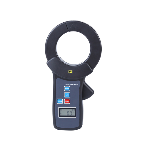
The GAOTek AC/DC Clamp Meter with On-Line Monitoring adopts the latest CT and digital integration technology. It has a large clamp and performs multiple additional functions such as peak holding, on-line monitoring, historical data inquiry, active curve drawing, data storage, printing, indication of max, min and average value, alarm value setting, and indication. It is widely used in the fields of electricity, communications, meteorology, railroads, oil, construction, scientific & research institutes, and industrial and mining establishments. It is an essential tool for electrician safety testing.
Features
- Compliant with IEC1010-1, IEC1010-2-032, Pollution degree 2, CAT III (600V) safety rules
- Resolution of 0.1 A
- Small sized and Large Clamp
- USB interface to upload data stored in the meter to PC
- Battery life of up to 100 hours
- Multiple functionalities
- Convenient data storage
- Automatic power off if idle time exceeds 5 minutes
- Four digit LCD display
Technical Specifications
| Range | DC: 0.0 A~2000 A
AC: 0.0 A~1500 A |
| Resolution | 0.1 A |
| Frequency | AC 45 Hz ~ 400 Hz |
| Test mode | Clip-on CT, non-contact mode |
| Power | Zn-Mn dry battery,6F22,9 V |
| Clamp size | Φ 2.6 in ( Φ 68 mm) |
| Accuracy | ±2 % rdg ±3 dgt |
| Dimension | 8.8 in × 4.5 in × 1.6 in (224 mm × 115 mm × 43 mm) |
| LCD dimension | 1.3 in × 0.8 in (35 mm × 21.5 mm)
Display Domain: 1.2 in × 0.5 in (32 mm × 15 mm) |
| Sampling rate | About 2 times/s |
| Range shift | Automatic |
| Polarity indication | DC Current Auto identified and display“—” |
| Test position | Tested wire in the jaw centre; Error will increase to 1.5 % rdg max if deviated the from centre |
| Line voltage | 600 V AC |
| Data memory | 99 units, FULL blinks when the memory is full |
| Battery voltage indication | Below 7.2 V |
| Consumption | 10 mW |
| Weight (including the battery) | 1.1 lbs (0.51 Kg) |
| Max error refer to environment | 14 °F ~ 32 °F (-10 ℃~0 ℃) and 104 °F ~ 122 °F (40 ℃~50 ℃). Error may increase to 1% rdg max |
| Temperature and humidity | Working: 14 °F ~122 °F (-10 ℃~50 ℃), below 80 % RH
Storage: 14 °F ~140 14 °F (-10 ℃~60 ℃), below 70 % RH |
| Insulating strength | AC 2 kV/rms (between the alloy of the clamp and the housing) |
Additional Information
Warning
- Under any circumstances, please pay special attention to your safety in the course of using this Clamp Meter
- Give heed to label texts and symbols on panel and back plate of this Clamp Meter
- Please be more careful if the line voltage is above 60 V DC or 30 V AC
- Put the tested wire through the geometrical centre of the jaw when measuring AC current, error will increase if deviated from the centre
- Please don’t place and store this device in hot and humid condition, locations with moisture condensation and under direct sunlight for a long time
- In case voltage of the battery is low, please replace the batteries
- In case this Clamp Meter is used for a long time, please take out the batteries
- When changing batteries, please pay attention to polarity of the battery
- Use, disassembly and maintenance of this meter shall be operated by authorized personnel
- In case of any danger with use of this meter, please stop using it and seal it for safekeeping immediately; and then, send it for disposal to the authorized agency
- Users shall carry out operation based on danger
 signs on the meter
 - Users shall carry out safety operation based on instructions listed e.g. “
 ” and danger signs on this manual
 - Please use am to test leakage current (test by clamping grounding and single-phase line together)
Range and Accuracy
| Function | Measure Range | Accuracy | Resolution |
| DC current | 0.0 mA~6.00 A | ±2%rdg±5dgt | 0.1mA |
(Condition: 73 °F ±5 °F, below 75% RH, wire in the centre of the jaw)
Electrical Signs
| |
Extremely dangerous! Operators shall strictly observe safety rules; otherwise there would be dangers of electric shock which may cause personal injuries or casualties |
| |
Dangerous!Operators shall strictly observe safety rules; otherwise there would be dangers of electric shock which may cause personal injuries or casualties. |
| |
Warning!Operators shall strictly observe safety rules; otherwise personal injuries or equipment damages might be caused. |
| |
Double insulation |
| |
AC |
| |
DC |
Structure of the DC Clamp Meter

- Double input toroid
- Toroid opening lever
- key
- LCD
- RS232 interface
- Positive direction
- Key
 AC/DC switch key
- Adjust 0 key
- Housing Screws (3 PCS)
- Battery cover screw
- Battery cover
LCD Display

- DC indication
- AC indication
- Negative polarity indication
- Low battery symbol
- Data hold indication
- Stored data code
- Unit of current indication
- Value of current
Operation
1. Start-up, Shutdown
- Press key to start up, LCD display will be turned on
- Press the key again to shut down the meter
- After starting up, if the Clamp meter is left idle for 5 minutes, the LCD displays a message that the meter will shut down automatically. After flickering for 30s, it will shut down formally to reduce battery consumption
- In case key is pressed when the LCD was flickering, the meter will continue to work for 5 minutes
- In case the LCD display is very low, charge the battery
2. AC/DC Measurement Switch
The meter defaults to DC measurement after boot up. Press ![]() to switch to AC/DC function. LCD will display DC or AC to corresponding switch function.
to switch to AC/DC function. LCD will display DC or AC to corresponding switch function.
3. DC Calibration
Before measuring DC current, press DCA ZERO key to reduce the residual magnetism to Zero and then conduct the measurement. Rational usage of this Adjust Zero function will make the results more accurate. For example, after boot, before measurement, we can take the jaw close to the DC current wire. LCD will show an inductive current. Press DCA ZERO to calibrate, which deducts the inductive value. This is shown below:


4. Current Measurement
| High voltage, extremely dangerous! Operators shall strictly observe safety rules; otherwise there would be risk of electric shock which causes personal injuries or casualties. | |
| |
Dangerous!Please don’t use it to measure current higher than 300 A; otherwise there would be risk of electric shock which causes personal injuries or equipment damages. |
- Power on
- Press
 for DC or AC measurement. Adjust Zero before measuring the DC current.
 - Release the toroid lever to open input toroid and clamp measured conductors. Be careful to see that the two input toroid must be totally closed and the measuring wire is passing through the centre of the jaw
- Read LCD display data. In case OL am symbol was displayed, it means that the current of measured line is beyond the maximum limit of this meter; In this case, please choose meter with much higher range limit


| |
Attention! For your safety, when measuring heavy current, after confirmation of the completion of correct operating test, please move the meter away from measured conductor |
| In locations where the data is difficult to be read, please use the data holding function. If [DH] symbol is displayed, please discharge data holding state first, and then do the test |
5. Peak Holding
Press HOLD key continuously in the course of measurement (More than 3 seconds), the meter will capture current peak values of lines in this period of time. After releasing the key, it will then return to the measuring state.
6. Hold, Storage and Access Reading
- Press key for a short time in the course of measurement (less than 3 seconds), symbol will display. The leaker will hold current measuring data and automatically store in the memory with a unit ID. Press key again to release the hold state and the leaker will continue to measure data. In case stored data reached to 60 groups, press key again and the “” symbol will display, which means storage memory is full; press key to cancel
- Press + keys to enter into data access mode and display Unit 1 storage data automatically. Then press key again to turn to the page of stored data. will display when there is no data stored in the memory. Press key to exit data access mode
- After entering into data access mode, press key for more than 3 seconds to clean up all stored data. When the leaker displays “” symbol, it means that it has finished clean-up process, and then returns to the measuring state automatically.
7. Data Upload
Connect the RS-232 or USB communication wire of the Tester. Switch on the Tester and run the monitoring software. If the software displays that the interface is open and the connection is successful, then the stored historical data can be read, uploaded and preserved.
Monitoring software has the function of online real-time monitoring and historical inquiry, dynamic display with the maximum, minimum and average value indication, alarm value settings and indicator, function of historical data access, reading, storage, print and other functions.
How to Change Battery
| |
Warning! It is dangerous to carry out test when the battery cover plate is not on its position. |
| Please pay attention to the polarity of battery to avoid damaging the leaker | |
| Chang the low battery in time | |
| If you expect not to use the meter for a long time, please get off the battery to storage |
- “
 ” symbol means the battery is low and need to be replaced
 - Press key to shut down the meter. Before opening the battery cover, please confirm the meter is in off position and then replace
- With qualified new battery, special attention shall be paid to the polarity of battery. Cover the battery cover plate
Accessories
| Clamp tester | 1 pc |
| USB Com cable | 1 pc |
| Software | 1 disk |
| Battery (6F22 9 V) | 1 pc |
| User Manual | 1 copy |
| Warranty card / Certification | 1 copy |


