
GAOTek Digital Storage Oscilloscope
This digital storage oscilloscope analyses up to 4 analog channels with a sampling rate of up to 500 MSa/s and offers a remarkable bandwidth combined with sufficient storage and makes accurate measurements
Description
Overview
GAOTek Digital Storage Oscilloscope integrates a digital oscilloscope, a logic analyzer, a FFT spectrum analyzer, an electronic counter and a clock Jitter analyzer into one device. This device offers a remarkable bandwidth combined with sufficient storage which allows to make accurate measurements. The module efficiently solves complicated trigger problems by providing a comprehensive set of triggers such as rising or falling edge, pulse width, delayed and count. It allows to effectively measure and record signals for playback and evaluation. This Oscilloscope is cost effective since it is PC based that consists of a specialized signal acquisition board which is an external USB and it is is commonly used for the maintenance of electronic equipment and laboratory work. It is also suitable for field use in sciences, medicine, engineering and telecommunications.
Key Features
- 5-in-1 design: digital oscilloscope, logic analyzer, FFT spectrum analyzer, electronics counter, clock jitter analyzer
- Up to 1 GS/s single shot sampling rate
- Up to 20 GS/s repeat sampling rate
- 170 MHz bandwidth
- Universal triggering with 512 trigger levels:
- Several types of triggering: I2C, SPI, UART, cross trigger, pre-triggering, pulse width, TV (NTSC525, PAL625) triggering and count.
- 8 channel logic analyzer crossing trigger to analog channel, vice versa.
- Deep 4 M/8 M sample data acquisition buffers on each channel (A1, A2, A3, A4, D0 to D7)
- Precision 125 MHz frequency counter, up to 7 digital resolution at 1 M memory for each analog channel
- Fast Fourier Transformations (FFT) function for bandwidth testing
- Convenient timing state display for logic debug
- X-Y Plot
- Multi-Window software
- DLL Libraries (optional)
Technical Specifications
| Sampling rate | 2 Ch: 2 MSa/s to 1 GSa/s
4 Ch: 1 Sa/s to 500 MSa/s |
| Record length | 2 Ch–2 K/32 K/256 K/2 Mega
4Ch–1K/16 K/128 K/1Mega |
| External clock | 0 to 100 MHz for Logic Analyzer
10 to 100 MHz for analog Channel 200 KΩ/4 pf, +/-50 V max |
| Power supply | DC Adapter 6 V/3.0 A |
| PC interface | USB 1.1/2.0 |
| Net weight | 3.9 lbs (1.8 Kg) |
| Size (Dimension) | 9.0 in x 5.5 in x 1.5 in [230 mm x 142 mm x 40 mm] (aluminium case) |
| Analog Channel | |
| Analog channel | 4Ch (Ch.A1, Ch.A2, Ch.A3, Ch.A4) |
| Input bandwidth | 2 Ch DC – 170 MHz
4 Ch DC – 125 MHz |
| Trigger level(Universal) | 512 Levels |
| Spectrum FFT | 150 MHz(Fast Fourier Transform) |
| Math | +,- |
| Multi window | Yes |
| Maximum input voltage | +-50 V |
| Input impedance | 1 Mohm//15pF |
| Digital Channel | |
| Digital channel | D0 – D7 (8 Ch)
D0~D31 (32 Ch)[Expand Pod] |
| Input bandwidth | D0 – D7 (8 Ch) DC –100 MHz
D0~D31 (32 Ch) DC – 10 MHz [Expand Pod] |
| Record length | 1 Mega |
| Maximum input voltage | +-50 V |
| Trigger level(Universal) | 512 Levels |
| Input impedance | 200 K ohm//4 pF |
Hardware Installation
- Turn off the computer and all peripheral connected. Remove the computer power cord from the wall outlet
- Locate an available USB interface (USB 2.0 version)
- Connect the included USB cable to USB interface
- Plug in power source from +5.75 V / 2.5 A DC Adapter
- After checking all connections, turn on the computer peripherals. You are now ready to install the software
Software Installation
- Insert the distribution CD into the CD driver
- Select the File menu
- Enter file to run setup.exe installed in the CD drive
- Follow the on screen instructions
Applications
- Testing of signal voltage in radio broadcasting equipment and circuit debugging
- Jitter and power analysis
- For research and design
- Cursor and pulse width readings
- Rise time and propagation delay measurements
- Acts as a simple signal tracer
- Measurement of the functions of the individual component of the device
- Measurement of components’ minor variations in operations
- Prevention of erroneous replacement of parts
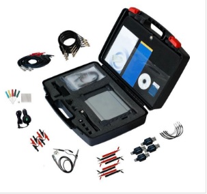
Standard Accessories
Logic analyzer pod, Calibrated probe (1:1, 10:1) × 4 pcs, housing with wires and clips × 36 pcs, USB 2.0 cable, Software CD, DC Adapter 5.75 V/ 2.5 A