
Description
Overview
GAOTek 4-Channel Automotive Tester/Diagnostic Oscilloscope is a small, lightweight, and a portable oscilloscope. No external power is required for this Oscilloscope. It has a wide input voltage range from 8 V to 36 V which makes it suitable for vehicle power tests. This oscilloscope is powered directly from the USB port of a computer, so this kit can be used either in the workshop or on the road to test and measure virtually all of the electrical and electronic components and systems in motor vehicles. It is also ideal for production test, research and design and all of the applications involving analog circuits test and troubleshooting, as well as education and training.
Key Features
- 4 Channels and EXT trigger, 60MHz Bandwidth.
- 200MS/s real-time sampling rate, 10k – 16M memory depth per Channel.
- Automatic setup for ease of use (AUTOSET).
- More than 20 kinds of automatic measurement and PASS/FAIL Check function, which is suitable for engineering application.
- Excellent industrial design, similar interface with bench oscilloscope, Easy to use.
- Frequency Counter; built-in Fast Fourier Transform (FFT) function.
- Automatic cursor tracking measurements.
- Waveform storage, record and replay dynamic waveforms.
- User selectable fast offset calibration.
- Add, Subtract and Multiply Mathematic Functions.
- Selectable 20 MHz bandwidth limit.
- Waveform average, Adjustable waveform intensity, more effective waveform view.
- User interface in several user-selectable languages.
- 8 V – 36 V Wide range of input voltage, suitable for vehicle power test.
- USB 2.0 interface plug and play, LAN optional.
- Software support: Windows NT, Windows 2000, Windows XP, VISTA, Windows 7.
- Vehicle Diagnosis:
- First Diagnosis (Cranking Exhaust Diagnosis)
- Ignition Action (Current/Voltage)
- The Sensor (Air Flow Meter, Camshaft, Crankshaft)
- Bus Diagnosis (CAN Bus Data View)
- Performer (Petrol/Diesel)
- Startup & Charge (Charging Circuits Current/Voltage)
Applications
- Suitable for vehicle power tests.
- Ideal for production test, research and design and all of the applications involving analog circuits test and troubleshooting, as well as education and training.
Technical Specifications
| Input | |
| Max. Sample rate | 200 MS/s (single channel)
100 MS/s (dual channels) |
| Channels | 4 channels |
| Bandwidth | 60 MHz (-3 dB) |
| Vertical resolution | 8 bits/channel |
| Gain range | 10 mV to 5 V/div at x 1 probe (10 mV, 20 mV, 50 mV, 100 mV, 200 mV, 500 mV, 1 V, 2 V, 5 V/div 1, 2, 5 sequence)
100 mV to 50 V/div at x 10 probe 1 v to 500 V/div at x 100 probe 10 v to 5 KV/div at x 1000 probe |
| Range | 8 divisions |
| Offset level | ± 4 divisions |
| Coupling | AC, DC, GND |
| Offset increments | 0.02 div |
| Impedance | 1M ohm |
| DC accuracy | ± 3% |
| Input protection | 35 Vpk (DC + peak AC < 10 KHz, without external attenuation) |
| Display mode | Y-T, X-Y |
| Timebase | |
| Timebase range | 5 ns/div to 1000 s/div (1-2-5 sequence) |
| Acquisition mode | Real time sampling: 5 ns /div to 200 ms/div.
Roll mode: 500 ms/div to 1000 s/div |
| Range | 10 divisions |
| Buffer size | 10 K to 16 M points (Single Channel) |
| Trigger | |
| Type | Edge trigger, pulse trigger |
| Mode | Auto, Normal and Single |
| Autoset | Yes |
| Range | 10 divisions |
| Trigger level | ± 4 divisions |
| Stability | 0.02 div increments |
| Math | |
| Measurements | Vpp, vmax, vmin, vmean, vrms, vamp, vtop, vbase, vmid, positive overshoot, negative overshoot, cycle mean, cycle RMS, period, frequency, positive pulse width, negative pulse width, rise time (10 %~ 90 %), fall time (10 % to 90 %), positive duty cycle, negative duty cycle |
| Math | Addition, Subtraction, Multiplication, FFT |
| FFT | Rectangular, Hanning, Hamming, Blackman Window |
| Physical | |
| Interface | USB 2.0 (USB 1.1 compatible) |
| Power | External power source required (8.5 V DC) |
| Dimensions | 19.29 in x 6.5 in x 16.14 in (490 mm x 165 mm x 410 mm) |
| Weight | 16.5 lbs (7.5 kg) |
Ordering Information
| A0E20001tek – Kit III | A0E20001tek – Kit V | A0E20001tek – Kit VII | |
| Package | Aluminum Toolcase | ||
| Test Leads with BNC plug and Aligator clip | 2 | 2 | 2 |
| Auto Test Leads | 4 | 4 | 4 |
| Auto Ignition Probe | 1 | 4 | 4 |
| 20:1 Attenuator | 2 | 4 | 4 |
| Large Dolphin/Gator Clip | 2 | 4 | 4 |
| Multimeter Probe | 2 | 4 | 4 |
| Acupuncture Probe Set | 1 | 1 | 1 |
| Break Out Leads | 1 | 1 | 1 |
| Coil-on-Plug Extension Cord (with earth cord) | 0 | 4 | 4 |
| Auto Power Adapter | 0 | 1 | 1 |
| 65A AC/DC Current Clamp | 0 | 0 | 1 |
| 650A AC/DC Current Clamp | 0 | 0 | 1 |
Packaging List
| S.no | ITEM DESCRIPTION | QUANTITY |
| 1 | Auto Test Cable | 4 |
| 2 | Auto High-Pressure Ignition Probe | 4 |
| 3 | Attenuator | 4 |
| 4 | Large Dolphin/Gator Clip | 4 |
| 5 | Multimeter Probe | 4 |
| 6 | Acupuncture Probe Set | 1 |
| 7 | Dolphin/Gator Clip Cable | 2 |
| 8 | Break Out Leads | 1 |
| 9 | Coil-on-Plug Extension Cord (with earth cord) | 4 |
| 10 | Auto Power Adapter | 1 |
| 11 | 65A AC/DC Current Clamp | – |
| 12 | 650A AC/DC Current Clamp | – |
| 13 | User Manual | 1 |
| 14 | PC Software | 1 |
Additional Information
Getting Started
The oscilloscopes are ideal for production test, research and design and all of the applications involving analog circuits test and troubleshooting, as well as education and training.
To run the oscilloscope software, the needs of computer configuration are as follows:
Minimum System Requirements
Operating System – Window NT/2000/XP/VISTA/Win7
Processor- Upwards of 1.00 G processor
Memory- 256 M byte
Disk Space –500 M disk free space
Screen resolution- 800 x 600 resolution
Recommended Configuration
Operating System- Windows XP SP3 System
Processor –2.4G Processor
Memory- 1G Byte Memory
Disk Space- 80G Disk Space
Screen resolution- 1024 x 768 or 1280 x 1024 resolution
DPI Setting- Normal Size (96DPI)
Install Software
Caution: You must install the software before using the oscilloscope.
- While in Windows, insert the installation CD into the CD-ROM drive.
- The installation should start up automatically. Otherwise in Windows Explorer, switch to the CD-ROM drive and run Setup.exe.
- The software Installation is started. Click ‘Next’ to continue.
- Choose a destination directory. Click ‘Next’ to continue.
- Check the setup information. Click Next to start copying of files.
- This Status dialog is displayed during copying of files.
- Updating Your System Configuration.
- The installation is complete.
Install Driver
- Connect the A-Type Plug of USB cable to your PC’S USB port.

2. Connect the B-Type Plug of USB cable to the product USB port.

- New hardware is found.
- Select the specific location.
- New hardware search wizard starts to search the driver.
- New hardware wizard installs the product.
- The wizard has finished installing.
Probe Compensation
Perform this function to match the characteristics of the probe and the channel input. This should be performed whenever attaching a probe to any input channel at the first time.
- From the “Probe” menu, select attenuation to 1:10. Set the switch to “X10” on the probe and connect it to CH1 of the oscilloscope. When using the probe hook-tip, insert the tip onto the probe firmly to ensure a proper connection.
- Attach the probe tip to the Probe Compensator and the reference lead to the ground connector, select CH1, and then press the “AUTOSET“ button into the menu or the toolbar.
- Check the shape of the displayed waveform.


- If necessary, use a non-metallic tool to adjust the trimmer capacitor of the probe for the flattest square wave being displayed on the oscilloscope.
- Repeat if necessary.
WARNING:
To avoid electric shock while using the probe, be sure the perfection of the insulated cable, and do not touch the metallic portions of the probe head while it is con-nected with a voltage source.
Function Check
Perform this functional check to verify that your oscilloscope is operating correctly.
■ Connect the oscilloscope
You should connect the A-Type Plug of USB cable to your PC USB port and connect the B-Type Plug of USB cable to oscilloscope USB port.
■ Input a signal to a channel of the oscilloscope
The oscilloscope is equipped with four channels plus external trigger.
Please input signal in the following steps:
- Set the attenuation switch on the probe as 10X and connect the probe on the oscilloscope with CH1. Aim the slot in the probe connector at the faucet on BNC of CH1 and insert, then, turn right to lock the probe. Finally, attach the tip of probe and ground nip to the Connector of probe compensator.

- Set the CH1 probe attenuation of the oscilloscope to X10. (The default is X1).
- Attach the tip of probe and ground nip to the Connector of Probe compensator. Click the button. A square wave will be displayed within a several seconds. (Approximately 1 kHz, 2V, peak- to- peak).
- Inspect CH2 ,CH3 and CH4 with the same method. Repeat steps 2 and 3.
Self Calibration
The self calibration routine lets you optimize the oscilloscope signal path for maximum measurement accuracy. You can run the routine at any time, but you should always run the routine if the ambient temperature changes by 5 V or more. For accurate calibration, power on the oscilloscope and wait twenty minutes to ensure it is warmed up. To compensate the signal path, disconnect any probes or cables from the input connectors. Then, access the “Utility -> Calibration” option and follow the directions on the screen. The self calibration routine takes about several minutes.
Standard Accessories


Optional Accessories


Optional Power LAN PCB


WIFI PCB Auto High-Pressure Ignition Probe


Attenuator Needle


Test Leads Coil-on Plug Extension Leads


Break Out Leads AC DC Current Clamp (CC-65)


AC DC Current Clamp (CC-650) AC DC Current Clamp (CC-1100)


Multimeter Probes Large Dolphin Gator Clips
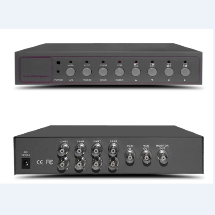
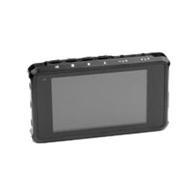
Other Images


