
GAOTek Digital Storage Oscilloscope
This digital oscilloscope is an all-in-one device which integrates the functions of a logic analyzer,
FFT spectrum analyzer,
electronics counter, clock jitters analyzer and comes with 8 channel logic analyzers
crossing trigger to analog channel and vice versa
Description
GAOTek digital storage oscilloscope integrates a digital oscilloscope, a logic analyzer, a FFT spectrum analyzer, an electronic counter and a clock Jitter analyzer into one device. The module efficiently solves complicated trigger problems by providing a comprehensive set of triggers such as rising or falling edge, pulse width, delayed and count. This oscilloscope is commonly used for the maintenance of electronic equipment and laboratory work, and it is suitable for field use in sciences, medicine, engineering and telecommunications.
Key Features
- 5-in-1 design: digital oscilloscope, logic analyzer, FFT spectrum analyzer, electronics counter, clock jitter analyzer
- Up to 1 GS/s single shot sampling rate
- Up to 20 GS/s repeat sampling rate
- 170 MHz bandwidth
- Universal Triggering with 512 trigger levels:
– Several types of triggering: I2C, SPI, UART, cross trigger, pre-triggering, pulse width, TV (NTSC525, PAL625) triggering and count.
– 8 channel logic analyzer crossing trigger to analog channel, vice versa.
- Deep 4 M/8 M sample data acquisition buffers on each channel (A1, A2, A3, A4, D0 to D7)
- Precision 125 MHz frequency counter, up to 7 digital resolution at 1 M memory for each analog channel
- Fast Fourier Transformations (FFT) function for Bandwidth test
- Convenient timing state display for logic debug
- X-Y Plot
- Multi-Window software
- DLL Libraries (optional)
Technical Specifications
| Sampling Rate | 2 Ch 2 MSa/s to 1 GSa/s by 1, 2, 5 sequence
4 Ch 1Sa/s to 500 MSa/s by 1, 2, 5 sequence |
| External Clock | 0 to 100 MHz for logic analyzer
10 to 100 MHz for analog channel 200 K ohm // 4 pF,±50 V Max
|
| Record Length | 2 Ch 2 K/32 K/256 K/8 Mega
4 Ch 1 K/16 K/128 K/4 Mega |
| Analog Channel | A1, A2, A3, A4 |
| Input Bandwidth | 2 Ch DC – 170 MHz
4 Ch DC – 125 MHz |
| Input Impedance | 1 Mohm // 15 pF |
| Max. Input Voltage | ±50 V (±100 V Transient) |
| Sensitivity | 10 mV/div to 4 V/div |
| Trigger Level (Universal) | 512 |
| Repetitive Mode | up to 20 GHz |
| Spectrum FFT | 150 MHz (Fast Fourier Transform) |
| Electronics Counter | max 7 digits resolution |
| X – Y Plot | allow to graph one channel to another |
| Math. | +,- |
| Multi-Window | Yes |
| Operate | Mouse |
| Digital Channel | MouseD0-D7 (8ch)
D0-D31 (32Ch) [Expand Pod] |
| Input Bandwidth | D0- D7 (8 Ch) DC – 100 MHz
D0-D31 (32 Ch) DC -10 MHz[Expand Pod] |
| Sampling Rate | D0 – D7 (8 Ch) 0 ~500 MHz
D0-D31 (32 Ch) 0 ~ 200 MHz[Expand Pod] |
| Record Length | 4 Mega
|
| Input Impedance | 200 Kohm // 4pF |
| Max. Input Voltage | ± 50 V (±100 V Transient) |
| Threshold Voltage | -1.8 V ~ +4.5 V |
| Trigger Qualify | 0,1, X (do not care) settings for all digital channels |
| Power Supply | DC Adapter 6 V/3.0A |
| PC Interface | USB 1.1/2.0 |
| Weight | 1.8 kg (3.96 lb) |
| Dimension | 9.05512 in *5.59055 in * 1.5748 in (230 mm x 142 mm x 40 mm) |
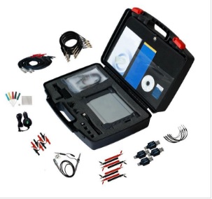
Accessories
User’s Manual, Calibrated Probe (1:1, 10:1) x 2 pcs. Logic Analyzer Pod, Housing with wires & clips x 36 pcs, USB 2.0 cable, Software CD, DC Adapter 5.75 V/2.5 A.
Guide to operation
When making measurements with the Digital Storage Oscilloscope/Logic Analyzer, meaningful data can only be captured with some prior knowledge of the characteristics of the circuit under test. Before initiating any capture cycles, the DSO must be configured using the control program.
To connect the DSO to the test circuit, there are two standard BNC probes, one for each analog input channel and a series of mini-clips on the logic analyzer Pod for the Logic input channels.
The scope probes have removable hook clips on their ends and an attached alligator clip for the signal ground connection. The Logic Analyzer Pod has inputs for 8 channels, D0 channel is the external clock input, and 3 ground points.
For synchronous data captures, external clock sources can be connected to the D0 channel.
At times, it may also be necessary to connect the test circuit to the computer system itself. This will eliminate more noise in the test application due to ground level differentials. This is especially true when dealing with high speed timing analysis. Use a heavy gauge wire to make a connection between the test circuit ground and the case of the computer. Each Analog channel probe has a calibration adjustment. It is important that this calibration be made at least twice a year.
Note 1: When connecting the probe to any signal, make sure that the signal voltage is within the limits of the DSO. Check the technical information section for absolute maximum and recommended maximum input voltage for the probes.
Logic Analyzer Pod Markings:
D0 ~ D7 Channel data inputs for the product.
(product support D0 ~ D3 only).
GND Signal ground connection.
The wires and the clips that come with the pods are modular. The pods, wires, and clips can all be disconnected from each other by gently pulling them apart. Removing just the clips, but leaving the wires connected to the pods allows connections to be made to wires and posts of the test circuit of up to 0.64 mm (0.025 in).
Note 2: Do not insert wires or posts greater than this diameter as that will expand the contacts in the wire beyond the allowed limited, possibly damaging the connector.