Description
Features
- Measure the Positive system grounding voltage, negative grounding voltage, system voltage in the voltage range of 0 to 300 V.
- Measure the Positive system grounding insulation resistance and negative grounding insulation resistance in the insulation resistance range of 0 to 999.9 KΩ.
- Detect the fault of AC fleeing into DC and can measure the AC Voltage value. The AC voltage value range is 0 to 280 V.
- Measure the Positive or negative grounding insulation resistance.
- Branch grounding fault Point Location function.
- It can be used as a high-precision ammeter.
- It can detect the system grounding on no signal to the system.
- Grounding direction display function.
- Insulation Index display function.
Applications
- Can be used to detect the indirect grounding, non-metal grounding, loop grounding, positive and negative at the same time grounding, positive and negative balance grounding of the DC system
- Can be used to detect the AC into DC Fault, multi-point grounding of the DC system.
Technical Specifications
| Specifications of Analyzer | |
| Applicable DC system voltage levels | 48 V, 110 V, 220 V |
| System voltage measurement range | 0 to 300 V |
| DC to the ground voltage measurement range | 0 to 300 V |
| AC to the ground voltage measurement range | 0 to 280 V |
| Voltage measurement resolution | 0.1 V |
| System grounding resistance measurement range | 0 to 600 KΩ |
| Grounding resistance measurement resolution | 0.1 KΩ |
| Detection signal current size | 0 to 2 Ma |
| Detection signal voltage amplitude | 0 to 50 V |
| Signal frequency | 0.167 Hz |
| Display mode | LCD |
| Specifications of Detector | |
| Branch insulation resistance detection range (under signal mode) | 0 to 600 KΩ (220 V),
0 to 300 KΩ (110 V), 0 to 60 KΩ (48 V) |
| Branch insulation resistance detection range (under no signal mode) | 0 to 50 KΩ (220 V),
0 to 25 KΩ (110 V), 0 to 10 KΩ (48 V) |
| Insulation resistance measurement resolution | 0.1 KΩ |
| Waveform display time | 12 s |
| Current measurement range | ±50 mA |
| Current measurement resolution | 0.01 mA |
| Clamp size | Ф 1.3 in (30 mm) |
| Display mode | LCD |
| Direction display | up arrow indicates same direction and down arrow indicates inverse direction |
| Wireless Communication | |
| Signal power | ≤ 10 dBm |
| Signal band | 433 Mhz |
| Sensitivity | -106 dBm |
| Transmission distance | In the range of visibility, the reliable transmission from the ground 2 m distance of 100 m. |
| Environmental Specification | |
| environment temperature | -5 °C ∼ +50 ℃ (23 °F ∼ 122 °F) |
| Relative humidity | ≤ 90% |
Packaging List
| Sr. No. | Item description | Quantity |
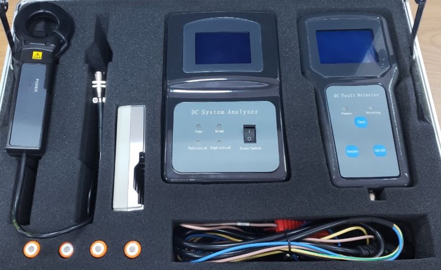
| 1 | DC System Analyzer | 1 |
| 2 | DC Fault Detector | 1 |
| 3 | DC clamp | 1 |
| 4 | AA batteries | 4 |
| 5 | Charger | 1 |
| 6 | Three core cable | 1 |
| 7 | User manual | 1 |
| 8 | Certificate | 1 |
| 9 | Warranty Card | 1 |
| 10 | Suitcase | 1 |
Additional Information
Equipment Appearance and Function Keys:
Appearance of the Analyzer

Appearance of the detector

Operation Method
- Put “Analyzer” into the DC system
Turn off the power switch of the Analyzer. Put one end of the power line in the Analyzer and the other end of the power line in the DC system according to the color of each positive, negative and ground.
Brown: positive; Blue: negative; Yellow/green: ground.
Then turn on the power switch of the Analyzer. The main interface of the Analyzer is as shown below:

Sys_Vol: DC system voltage.
Pos_Vol: DC system positive to the ground voltage (or Neg_Vol: DC system negative to ground voltage): If positive to the ground voltage is less than negative to the ground voltage, it will display as positive to the ground voltage, else it will display as negative to the ground voltage.
AC_Vol: AC into DC voltage: If AC voltage less than 5V, it will display as “No”, else it will display the AC voltage.
GND_Res: DC system positive to the ground or negative to the ground resistance: If the absolute difference value of positive to the ground voltage and negative to the ground voltage is more than 15 V, it displays the positive to ground resistance or negative to ground resistance which is lower, else it will display the mode value which is 992.0KΩ to 999.0 KΩ according to the mode set.
If the absolute difference value of positive to the ground voltage and negative to the ground voltage is more than 15V, the Analyzer will launch the test bridge, else the Analyzer will not launch the test bridge.
- “Detector” self-inspection
Turn on the Detector: Open the battery cover. Put the 4 batteries in the battery compartments according to the battery pole. Press the power button to turn on the Detector . The main interface of the Detector is as shown below-

Self-inspection: When the Analyzer launched test bridge, we can operate the Detector to self-inspection. Clamp clamped the ground line connected to the Analyzer. Press the “Function” button to select the “Grounding Test” or ”Insulation Test” function, then press the “Test” button to launch test. If selected “Grounding Test” function to test, enter the “Grounding Test” interface as shown below-


Communication success: indicate the communication between Analyzer and Detector success or failure. If communication fails, check if the “Analyzer” has launched the test bridge or retest it.
Current waveform: Description of the change of the leakage current waveform to the ground. If the “Analyzer” has launched the test bridge, there will be a periodic leakage current waveform. The waveform’s period is 6 second and the waveform is a square wave.
Ground level: indicate the ground level by number 0 to 99. Larger the number, worse the ground level.
Ground Direction: A up arrow indicate the ground fault point direction is the same as the direction marked in the clamp. A down arrow indicates the ground fault point direction is the inverse direction marked in the clamp.
Ground or No Ground: If the number of ground level more than 60, it will display the ground, else it will display No Ground.
If select the “Insulation Test” function to test- Enter the “Insulation Test” interface and the diagram will be as shown below:

Communication success, Ground Direction: The same as the Ground Test.
Ground Resistance: the measurement of the ground resistance is the branch being tested. It calculated by the change of the ratio of the voltage wireless transferred by Analyzer and current.
Current waveform: The feature is the same as the Ground Test, but the sensitivity is double of the Ground Test.
When the ground resistance value is larger, the change of current will be smaller. Use the “Insulation Test” function to identify the fault current waveform more clearly.
We suggest using “Insulation Test” function to locate the ground fault point.
- Start fault detector
Clamp clamped the branch line being tested. Press the “Function” button to select the “Grounding Test” or ”Insulation Test” function, then press the “Test” button to launch test. Holding clamp doesn’t shake in the testing process. Shaking will affect the test accuracy.
According to the test result and the current waveform to judge the branch line has a ground fault or not.
There are some test result and the current waveform for reference.


- Current Test
Follow the instructions to complete the current test function:
- Connect the clamp table to the Detector. Keep the clamp table in a natural state, don’t clamp any current branch, and make it closed normally. Go through the function menu to select the current test, press the test button to enter the function interface. Every time, enter the current test interface from the function menu interface, the detector will record the current measurement of the clamp table as zero.
- Put the clamp table into the tested branch. LCD will display the measurement of the leakage current of the tested branch. The diagram below is the current test function diagram.

Current: current measurement of clamp table of tested branch.
State: the state of the tested branch. It can display three states which are- Normal、Abnormal 、the resistance and direction of the tested branch.
If the current measurement value is less than 0.8mA, State will display Normal. If the current measurement value is more than 0.8mA and less than 10mA, state will display resistance and direction of the tested branch. If the current measurement value is more than 10mA, State will display Abnormal.
The resistance of the tested branch is the ratio of the positive to the ground voltage or negative to ground voltage which is lower and the current measurement. The voltage is getting from the Analyzer by wireless communication.
The State will be displayed when the communication between Analyzer and Detector is successful.
Note:
Under the current test interface, press the “test” button will reset the current value.
In order to ensure the accuracy of measurement, the range of the current test is less than 50mA. We use it to measure the leakage current. Usually, we clamped both positive and negative line of the tested branch by clamp table. If the Analyzer is in “No signal” mode, the resistance of the tested branch is referenced. If Analyzer is in the other mode, the resistance is unreliable.
- Work mode set of Analyzer
Analyzer provides four DIP switches on the side of the Analyzer, change this DIP switch can change the work mode of Analyzer. The fourth DIP switch is invalid, DIP switch in the ON state when unplugged, DIP switch settings and the top three gears relationship are as follows.

The device factory default mode is 998.0 mode.
Compulsory mode: under the compulsory mode, when the test bridge of Analyzer is launched, it will not be quiet.
Non-compulsory mode: under the non-compulsory mode, when the test bridge of Analyzer is launched, it will be quit by ground resistance change of the tested DC system.
if Analyzer retest the DC system is normal, the test bridge will be quiet. And if Analyzer retest the DC system is abnormal, the test bridge will be relaunched.
Under the 996.0 mode, whether the tested DC system is normal or abnormal, the test bridge is not launched.
- Display Over Range: when we test some branch line, the Detector will display the following interface:

If the Detector display “Adjustment Please Wait” interface, indicates the current through the clamp table is more than a value, Detector launch the negative feedback current by the coil around on the clamp to against the current. If the negative feedback current can against the tested branch current, the test will continue. Else Detector will display “Over Range”.
The negative feedback current is less than 2A if the tested branch current is more than this current, cannot be tested.
In this case, we need to clamp both the positive and negative of the tested branch by clamp table to test.
- The communication distance
If the Detector completes the self-inspection and communication with the Analyzer successful. The Detector will record the communication data and can be used in any place of the DC system, As long as you don’t turn off the Detector power.
- The communication distance
If the Detector completes the self-inspection and communication with the Analyzer successful. The Detector will record the communication data and can be used in any place of the DC system, As long as you don’t turn off the Detector power.
- The connection position of Analyzer
Connect the power line of Analyzer to the tested DC system bus, not some branch line.
- Since the unit is a precision instrument, during transport, use and storage must be handled with care, To prevent the fall and strong of the components, ensure high accuracy using.
- Each time you open the front detector detects, between the detector and analyzer a signal to be synchronized, synchronization required to maintain a distance of 5 meters between the detector and analyzer, after the signal synchronization is complete, detector can stay away from the analyzer, when using, keep the detector turned on after signal synchronization.
- After the completion of each use, detector batteries need to pull out from the battery compartment, after a full charge for the next use. When the low battery of detector, a battery should be replaced immediately to ensure the smooth testing conduct.
- Due to the high sensitivity of the clamp table, when detecting, the clamp should allow the clamp be a quiescent state, so as not to affect the detection accuracy.
- Due to the clamp of detector using staggered of tooth chip technology, when using, after opening the clamp pliers the wires, the clamp must be completely natural closure, if not natural closed, should be observed after the caution closure, cannot be applied vigorously forced closure, if forced closure, will result in the dislocation of the jaw teeth slice clamp damage.


