Description
Key Features
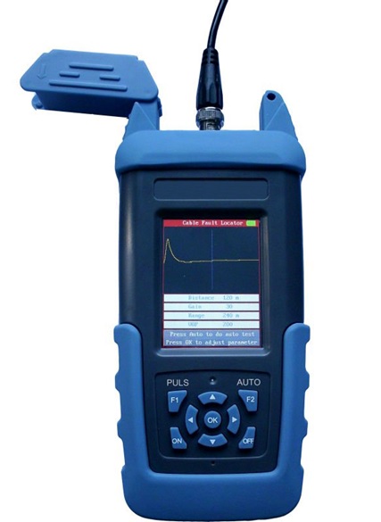
- Digital gain adjustment control to make the gain adjustment very easy.
- Automatic Identification technology of digital waveform to make sure no test dead zone.
- Top grade ARM single chip microcomputer can calculate and analyze the fault waveform exactly.
- Large color LCD display.
- High-energy Li-battery; supports continuous work of 10 hours (with special charger).
- Humanized operation interface; six function keys can do all the tests.
Applications
- Inspection of electrical and communication cables.
- Locating faults on cables.
- Detection of breaks, damage caused by moisture and other environmental factor.
Technical Specifications
| Maximum Working Range | 4.97 mi (8 km) |
| Highest Resolution | 3.28 ft (1 m) |
| Dead Zone | 0 ft (0 m) |
| Power Consumption | 1 W |
| Weight | 0.92 lbs (0.42 kg) |
| Dimension | 7.87 in × 3.54 in × 1.69 in (200 mm × 90 mm × 43 mm) |
| Operating Temperature | 5 ˚F to 113 ˚F (-15 ˚C to + 45 ˚C) |
| Storage Temperature | -4 ˚F to 131 ˚F (-20 ˚C to + 55 ˚C) |
| USB storage (optional) | Transmit waveform to U disk and analyze the waveform on computer. |
| Default Wave Velocity | 200 m/μs |
Packaging List
| No. | Item Description | Quantity |
| 1 | GAOTek TDR Cable Fault Locator | 1 |
| 2 | Rechargeable battery and charger/adapter | 1 |
| 3 | Test Line | 1 |
| 4 | CD (For USB Function) | 1 |
| 5 | U-disk (For USB function) | 1 |
| 6 | User Guide | 1 |
| 7 | Waterproof Carrycase | 1 |
Testing principles:
Steps of Locating Fault Point:
- Diagnosis of Fault Characters.
- Fault Testing.
- Locating Fault Point.
- Diagnosis of Fault Characters.
The characters of telecom cable faults can be divided into the following kinds:
- Broken Line
- Crossed Line
- Earthing Fault
- Crosstalk Noise
- Bad Insulation
- Fault Testing:
- To detect the fault cut off the cable from both ends either from lines or from equipment.
- Make sure the cable to be tested or free of voltage.
- Using this instrument detect using intelligence test first, if the fault cannot be detected then test should be done using Manual Testing.
Intelligence Auto Testing:
Switch on the instrument by pressing the “ON” button. Connect the lead line and fault cable line. Press the “AUTO” button the instrument will show the testing result by pressing the “AUTO” button.
Note: The default setting of wave velocity is 200 m/µs. To perform Intelligence testing user should check whether need to adjust the velocity.
| Reference Value for Common Cable Wave Velocity | |
| Insulators | Signal Propagation Velocity (m/µs) |
| High Polymer | 168-186 |
| Filled polythene | 192 |
| Polythene | 201 |
| Teflon | 213 |
| Paper pulp (0.13uF/Km) | 216 |
| Foamed polyethylene | 246 |
| Paper (0.117uF/Km) | 264 |
| 9.5mm coaxial (w) | 286 |
| 9.5mm coaxial (s) | 295 |
Manual Testing:
The manual testing can be performed by adjusting the setting and parameters. The relevant setting and parameters will demonstrate on the underneath of the display screen.
- Press “OK” button to adjust parameter and settings.
- GAIN- “Gain XX” shows reverse color display. “▲” or “▼” to display the amplitude (1~99 adjustable).After adjusting Gain press “PULSE” the screen will display the wave.
- Range- During manual testing range decides the maximum testing distance of the instrument. To adjust the Range, press “OK”, until “Range xx” shows reverse color display. Press “▲” or “▼” to adjust the Range.
- VOP- The precision of the wave velocity, directly affect the precision of the testing result. So the wave velocity shall be calibrated according to the cable characters. Press “OK”, until “VOP xx” shows reverse color display. Press “▲” or “▼” to adjust the Wave Velocity. Adjust the Range and VOP according to the characters and estimated length of the cable to be tested. Appropriately adjust the wave amplitude on the display screen to be observed easily. Move the cursor to inflection of the reflected waveform. The fault distance will demonstrate on the underneath of the display screen.
- Locating Fault point:
Tester will judge the approximate fault point location. Based on the testing result, then check with the cable, cable gland and cross boxes etc.
Pulse Testing:
It’s a kind of remote testing method. Fault point can be located without testing on the field (end to end co-ordination).
Formula for Pulse Testing:
Suppose the pulse transmission velocity in electric cable velocity is V, the come and back time that the pulse travels between the test point and the fault point is T, the fault distance is L, then:
- 2L = V T
- L = V T/2
Charge:
- Current battery power is showed at the top-right of the
- If the battery power is inadequate, use the instrument charger to charge it.
- The indicator light of the charge adapter will be red when charging; and it will turn green after it is fully charged.
Notes:
- Keep display screen away from direct sunlight.
- The contrast ratio of LCD will drop when temperature higher than 140 ˚F (60 ˚C) and it will return to normal when temperature is lower than 140 ˚F (60 ˚C).
- Before testing, measure the voltage of fault cable to be tested, in order to avoid test errors.
- Do not hit LCD screen.


