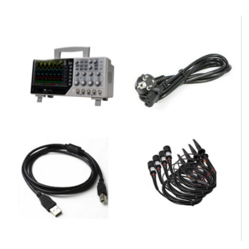
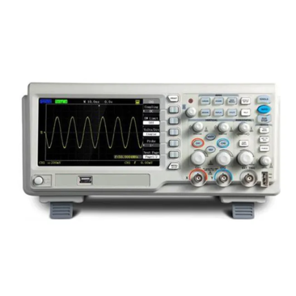
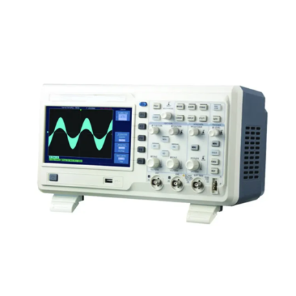
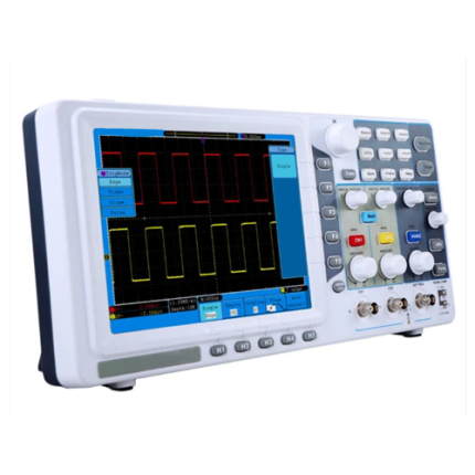
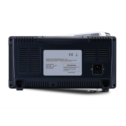
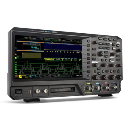
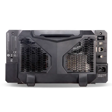
Description
Features
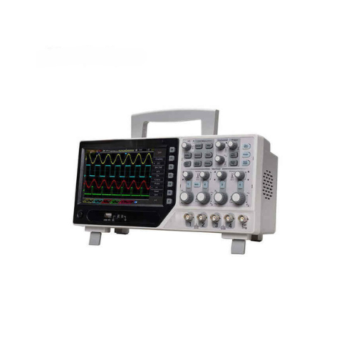
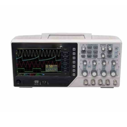
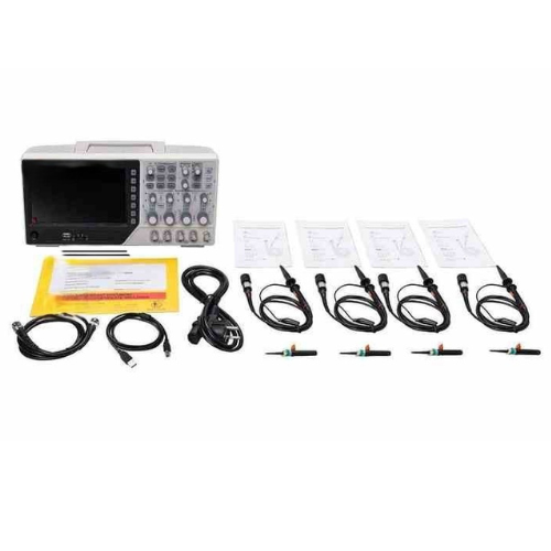
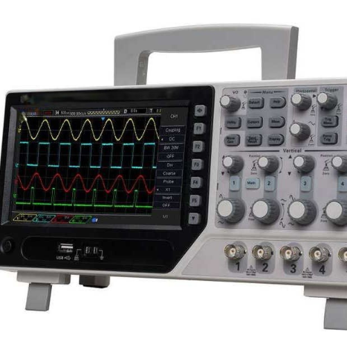
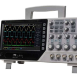
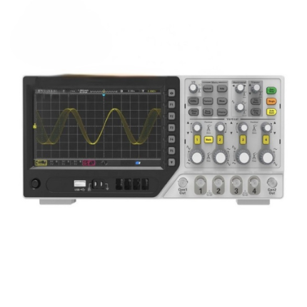
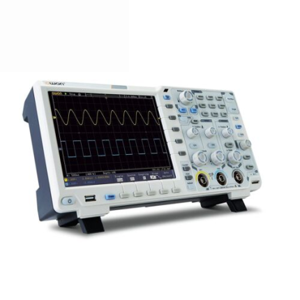
- 4 CH oscilloscope + EXT + DVM + auto range function
- 250 MHz bandwidth, minimum range 500 μV/div, 1 GS/s sample rate
- Over 32 types of auto measurement function
- Advanced digital trigger system, high trigger sensitivity
- Over 14 types of trigger function: edge, overtime, pulse, pattern, interval, etc
- Serial bus triggering and decode, Bus protocol information can be quickly and intuitively displayed in table form
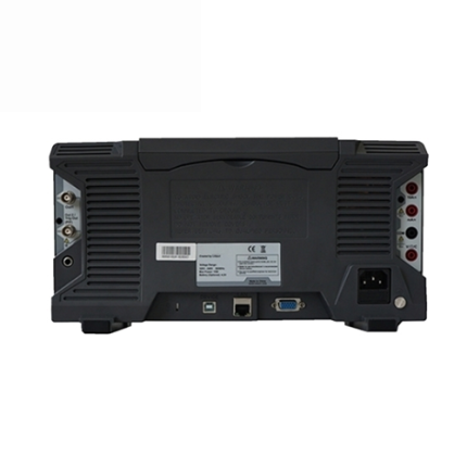
- Integrated USB Host or Device, convenient to communicate with PC. Support U-stick storage or system update
- Support a variety of SCPI remote control command
- Support optional RS232 port, LAN port (Optional)
- Stable and reliable quality, sturdy and durable
Technical Specifications
| Bandwidth | 250 MHz | |
| Sample Rate Range | 1 GS/s | |
| Waveform Interpolation | (sin x)/x | |
| Record Length | Maximum 64 K samples per single-channel;Maximum 32 K samples per dual-channel (4 K, 32 K optional)SEC or DIV Range | |
| SEC or DIV Range | 2 ns/div to 100 s/div1, 2, 5 sequence | |
| Sample Rate and Delay Time Accuracy |
± 50 Bppm | |
| Rise Time at BNC, typical | < 1.4 ns | |
| Mode | Auto, Normal | |
| Level | CH 1 to CH 4 | ± 4 divisions from center of screen |
| EXT | 0 V to 3.3 V | |
| Holdoff Range | 20 ns to 10 s | |
| Trigger Level Accuracy | CH 1 to CH 4 | 0.2 div × volts/div within ± 4 divisions from center of screen |
| EXT | ± (6 % of setting + 40 mV) | |
| Edge Trigger | ||
| Slope | Rising, Falling, Rising&Falling | |
| Source | CH 1 to CH 4 or EXT | |
| Under Amp | ||
| Polarity | Positive, Negative | |
| Condition (When) | <, >, ≠, = | |
| Source | CH 1 to CH 4 | |
| Time Range | 8 ns to 10 s | |
| Resolution | 8 ns | |
| UART Trigger | ||
| Condition (When) | Start, Stop, Data, Parity Error, COM Error | |
| Source (RX or TX) | CH 1 to CH 4 | |
| Data format | Hex | |
| Condition (When) | <, >, ≠, = | |
| Data Length | 1 byte | |
| Data Length | 5 bit, 6 bit, 7 bit, 8 bit | |
| Parity Check | None, Odd, Even | |
| Idle Level | High, Low | |
| Baud Rate (Selectable) | 110 bit/s or 300 bit/s or 600 bit/s or 1200 bit/s or 2400 bit/s or 4800 bit/s or 9600 bit/s or 14400 bit/s or 19200 bit/s or 38400 bit/s or 57600 bit/s or 115200 bit/s or 230400 bit/s or 380400 bit/s or 460400 bit/s | |
| Baud Rate (Custom) | 300 bit/s to 334000 bit/s | |
| LIN Trigger | ||
| Condition (When) | Interval Field, Sync Field, Id field, Sync Id Error, Identifier, Id and Data | |
| Source | CH 1 to CH 4 | |
| Data format | Hex | |
| Baud Rate (Selectable) | 110 bit/s or 300 bit/s or 600 bit/s or 1200 bit/s or 2400 bit/s or 4800 bit/s or 9600 bit/s or 14400 bit/s or 19200 bit/s or 38400 bit/s or 57600 bit/s or 115200 bit/s or 230400 bit/s or 380400 bit/s or 460400 bit/s | |
| Baud Rate (Custom) | 300 bit/s to 334000 bit/s | |
| CAN Trigger | ||
| Condition When) | Start Bit, Remote Frame, Data Frame Id, Frame Id, DataFrame Id A, Error Frame, All Error, Ack Error, Overload Fram | |
| Source | CH 1 to CH 4 | |
| Data format | Hex | |
| Baud Rate (Selectable) | 10000, 20000, 33300, 500000, 62500, 83300, 100000, 125000, 250000, 500000, 800000, 1000000 | |
| Baud Rate (Custom) | 5 kbit/s to 1 Mbit/s | |
| SPI Trigger | ||
| Source (CS or CLK or Data) | CH 1 to CH 4 | |
| Data format | Hex | |
| Data Length | 4, 8, 16, 24, 32 | |
| IIC Trigger | ||
| Source (SDA or SCL) | CH 1 to CH 4 | |
| Data format | Hex | |
| Data Index | 0 to 7 | |
| When (Condition) | Start, Stop, No Ack, Address, Data, Restart | |
| Inputs | ||
| Input Coupling | DC, AC or GND | |
| Input Impedance, DC coupled | 20 pF ± 3 pF, 1 MΩ ± 2 % | |
| Probe Attenuation | 1 X, 10 X | |
| Supported Probe Attenuation Factors | 1 X, 10 X, 100 X, 1000 X | |
| Overvoltage Category | 300 V CAT II | |
| Maximum Input Voltage | 300 VRMS (10 X) | |
| Measurements | ||
| Automatic Measurements | Frequency, Period, Average, Pk-Pk, RMS, PeriodRms, Min, Max, RiseTime, FallTime, + Width, – Width, + Duty, – Duty, Vbase, Vtop, Vmid, Vamp, Overshoot, Preshoot, PeriodAvg, FOVShoot, RPREShoot, BWidth, FRR, FFF, FRF, FFR, LRR, LRF, LFR and LFF |
|
| General Specifications | ||
| Display | ||
| Display Type | 7 in 64 K colour TFT (diagonal liquid crystal) | |
| Display Resolution | 800 horizontal by 480 vertical pixels | |
| Display Contrast | Adjustable | |
| Probe Compensator Output | ||
| Output Voltage, typical | About 2 Vpp into ≥ 1 MΩ load | |
| Frequency, typical | 1 kHz | |
| Power Supply | ||
| Supply Voltage | 100 V to 120 VACRMS (± 10 %), 45 Hz to 440 Hz, CAT Ⅱ 120 V to 240 VACRMS (± 10 %), 45 Hz to 66 Hz, CAT Ⅱ |
|
| Power Consumption | < 30 W | |
| Fuse | T, 3.15 A, 250 V, 5 in x 0.78 in (5 mm x 20 mm) | |
| Environmental | ||
| Operating Temperature | 32 °F to 122 °F (0 °C to 50 °C) | |
| Storage Temperature | -40 °F to 159.8 °F (-40 °C to +71 °C ) | |
| Humidity | ≤ +104 ℉ (≤ 40 °C): ≤ 90 % relative humidity | |
| 106 ℉ to 22 ℉ (+41 °C to 50 °C): ≤ 60 % relative humidity | ||
| Cooling Method | Convection | |
| Altitude | Operating and Nonoperating | 1.86 mi (3000 m) |
| Random Vibration | 0.31 gRMS from 50 Hz to 500 Hz,10 minutes on eaMETA axis | |
| Nonoperating | 2.46 gRMS from 5 Hz to 500 Hz10 minutes on each axis | |
| Mechanical | ||
| Dimension | 12.51 in x 4.33 in x 5.90 in (318 mm x 110 mm x 150 mm) ( | |
| Weight | 8.5 lb (3.9 kg) | |

