Description
Key Features
- Tests for open circuits, short circuits, cross connections, reverse connections, pairing connections in network cables, telephone cables, BNC cables, and USB cables
- Tests for crosstalk on network cable
- Efficiently locates the target cable among multiple cables
- Accurately determines short circuit position
- Measures cable length using three methods: M-S, M-R and OPEN
- Automatic power off and backlight function
- Lighting lamp enables to use in a dark environment
- Single chip software watchdog design runs reliably
- Low voltage prompt function is available
- Functions of storage and memory
- Remote unit with tone when checking wire map
Technical Specifications
| Testing Device Interface | Main Tester | RJ-45 (M), RJ-45 (S), loop interface, RJ11, BNC connector, USB B-type female interface | |
| Remote Identifier | RJ-45, RJ-11, BNC connector, USB A-type female interface. | ||
| Testing Cable Types | STP/UTP 5E, 6E network cable
Telephone cable Coaxial Cable USB cable Common metal wires connected with alligator clip. |
||
| Detecting cable types | STP/UTP 5E, 6E network cable
Telephone cable Coaxial Cable USB cable Common metal wires connected with alligator clip. |
||
| Length Measurement Range | 6561.68 ft. (2000 m) | ||
| Calibration Precision | 2% (+/-1.64 ft. (+/-0.5 m)) | ||
| Measurement Precision | 3% (+/-1.64 ft. (+/-0.5 m)) | ||
| Calibration cable | 32.8 ft. (10 m) | ||
| Power supply | Main Tester | 9V battery | |
| Receiver | 9V battery | ||
| Display | Dot matrix 5.04 in X 2.52 in (128 mmX64 mm)
Effective visible area 2.2 in X 1.57 in (56 mm X 40 mm) |
||
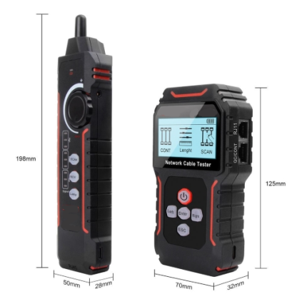
| Dimensions | Main Tester | 7.28 in X 3.14 in X 1.26 in (185 mm X 80 mm X 32 mm) | |
| Receiver | 8.58 in X 1.8 in X 1.14 in (218 mm X 46 mm X 29 mm) | ||
| Remote identifier | 4.21 in X 1.18 in X 0.94 in (107 mm X 30 mm X 24 mm) | ||
| Humidity | 20 % to 70 % | ||
| Operating Temperature | 14 ˚F to 140 ˚F (-10 ˚C to + 60 ˚C) | ||
Ordering information:
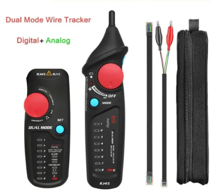
This package includes
| Item | Quantity |
| Emitter | 1 pcs |
| Receiver | 1 pcs |
| RJ11 Adapter cable | 1 pcs |
| RJ45 Adapter cable | 1 pcs |
| Remote adapter | 1 pcs |
| Alligator clip adaptor | 1 pcs |
| Earphone | 1 pcs |
| Kit | 1 pcs |
| Color Box | 1 pcs |
| User Guide | 1 pcs |
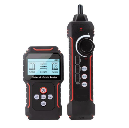
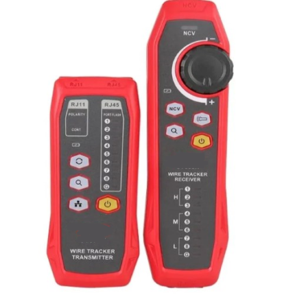
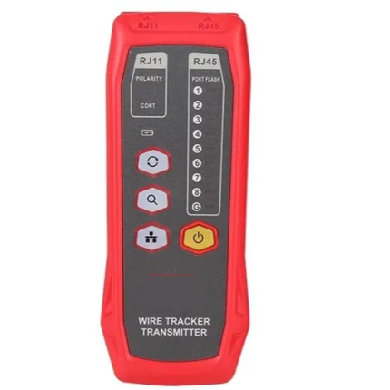
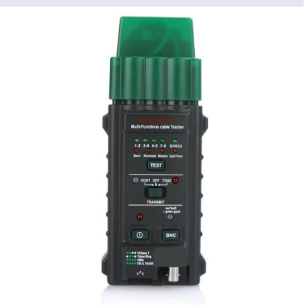
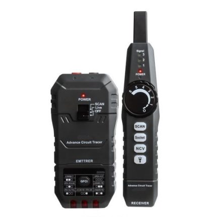
Product interface and key introduction

Main unit port instructions
- Two RJ 45 interfaces on the main unit: one of them is “MAIN” interface (“M” for short), and the other is “SCAN” interface (“S” for short); RJ 11 interface, USB interface and BNC interface
- M interface is used for measuring length and others, but not used for cable tracing; “S” interface is used for cable tracing test and “local” connection test.RJ11 interface, USB interface and BNC interface on the main unit are used for line-to-line, length testing and line tracing.
Product operation method
There are nine functional options in the main menu interface
- Language
- Wire mapping – Connection and disconnection test: To test connection of M, S R end-end cable and perform positioning of the failure.
- Cable Length -Pairing and length measurement: verify cable length, open circuit distance and pairing, crosstalk.
- Scan cable – To find target cable among lots of network cables, telephone cables, USB cables, coaxial cables and other kinds of wires.
- Type – Pair / Tel / USB / COAX / BNC Cable.
- Unit – Meter / Feet / Yards.
- Calibrate – Seven calibration coefficient can be stored in it. User can calibrate network/ telephone/ USB/ Coax cables.
- Data loading – Select the calibration coefficients stored in system.
- Auto power off— set the time for power off.
Cable line-to-line test:
To check wire map, press “ENTER” key. The following interface is shown indicating test is in process:

Test result 1: Short circuit
If there is short circuit with the cable and terminal, it will show as below: (Short circuit with 3 and 6)

Press any key to return to the main menu, and then press “ENTER” key for re-test. Do not perform the test until short circuit problem solved
Test result 2:
If the far end of the cable to be tested is not plugged in remote adapter (R) or cable is not plugged into the local port (S), the following interface is shown

Test result 3:
The following interface is shown when it is connected successful:

Test result 4:
In case of open circuit existing on far end of the cable, the following interface is shown:

In the above figure, “X” shown in “4” and “5” pin position, indicates there is open circuit in “4” and “5” pin of the remote pin.
Test result 5:
In case of open circuit existing at the near end of the cable, the following interface is shown:

In the above figure, “X” shown in “3” and “6” pin position in “M” line, indicates there is open circuit in “3” and “6” pin of the near pin.
Test result 6:
In case of open circuit existing at the middle part of the cable, the following interface is shown:

In the above figure, “X” shown in “3” pin position in “M” and “S” line, indicates there is open circuit in “3” pin of the middle part of the cable.
Test result 7:
USB cable line sequence test: Before checking wire map of USB cable, users need to choose “USB (4)” in “Type” and then return to main menu to check its wire map. If the testing cable is in perfect connection, the following interface will be shown:

Test result 9:
6-core telephone cable line sequence test: Before checking wire map of telephone cable, users need to choose “TEL (6)” in “Type” and then return to main menu to check its wire map. If the testing cable is in good connection, it will displays as follows:

Test result 10:
BNC coaxial cable line sequence test: Before checking wire map of BNC cable, users need to choose “BNC (2)” in and then return to main menu to check its wire map. If the testing cable is in good connection, it will displays as follows:

Cable length test:
Test length with the main tester. Do not connect cable into remote unit.
Insert one end of the testing cable into “M” port in the main tester when entering “Pair and Length” testing function to check the length. The following interface is shown:
Test result 1:
Short circuit:
If there is short circuit with the cable and terminal, it will show as below: (Short circuit with 3 and 6)
Press any key to return to the main menu, and then press “ENTER” key for re-test. Do not perform test until short circuit problem solved
Test result 2:
USB cable length test:
Insert one end of the USB cable to be tested into “USB” port of the main tester, the other end needs no connection, select “USB(4)” Type, return to the main menu, and select length test, and then press “ENTER” key to perform length test with the equipment, the following interface will be shown:

It indicates that length of USB cable is 10.1m. Now press any key to return to the main menu, and then press “ENTER” key for other testing.
Test result 3:
RJ11 (TEL) cable length test:
Insert one end of the RJ11 cable to be tested into “RJ11” port of the main tester, the other end needs no connection. select “Tel(6)” mode, return to the main menu, and select length test, and then press “ENTER” key to perform length test with the equipment, the following interface will be shown:
Press continuously “UP” or “DOWN” key, the following interface will be shown further:

It indicates length of telephone cable is 10.1m.
Test result 4:
BNC cable length test:
Insert one end of the BNC cable to be tested into “BNC” port of the main tester, the other end is an open circuit. Select “BNC (2)” mode, to return to the main menu, and then select length test. Press “ENTER” key to perform length test with the equipment, the following interface will be shown:

It indicates that length of BNC cable is 10.1m.
Cable tracing test:
Power on the main tester and enter main test menu, press “UP”, “DOWN” key to move cursor to cable scan, and then press “ENTER” key to find the line. The following interface will be shown:

Connect the cable to be found with the corresponding RJ-45 (Scan) port of the emitter, (RJ-11, USB or BNC). Take network line finding as an example: Connect the network cable to be found with RJ-45 port, move “ -> ” cursor to cable scan, and press “ENTER” key to perform line finding test as shown in the figure below:

Crosstalk Test:
As shown in the figure below: it shows 3, 6 and 4, 5 with crosstalk. The line pair with crosstalk will flash to indicate failure. If the testing cable is crosstalk, it will slow down the network speed.

Crosstalk interface is shown as below:

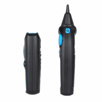
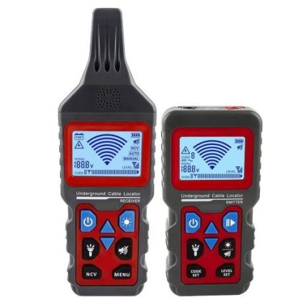
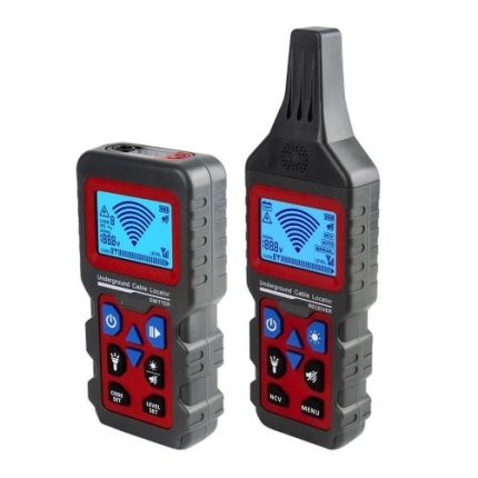
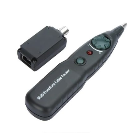
The usage of receiver:
Install 9 V battery, push the test key, and get close to the cables with probe. You can hear “beep” and the power led flashes. When the probe finds the targeted cable, the voice will be loud and the led light will be bright.
- Tracing cable (RJ-45/RJ-11 Cable) which is connected to switch or router.
Insert the cable into port RJ-11/ RJ-45 (S), Press the testing key of receiver, “Power” will glow, then hold the receiver close to the cables, when the probe gets close to the targeted one, you can hear clear and loud “beep, beep, beep” . (Note: telephone cable into RJ-11, LAN cable into port RJ-45(S)).
- Tracing Coax cable
Insert the cable into port BNC, Press the testing key of receiver, “Power” will glow, then hold the receiver close to the cables. When the probe gets close to the targeted one, you can hear clear and loud “beep, beep, beep”. (Note: turning down the voice slowly help trace cable easier).
- Locate the short or breakage point (e.g.: metal line)
Connect the metal line with the cable clips, press the testing key of receiver, hold the receiver close to the cables, “beep, beep, beep” will generate, but when the probe targets the breakage point, “beep, beep, beep” stops, which indicates that is where the breakage is.
Note:
- The metal line is de-energized.
- Turn up the voice, which helps to locate the breakage easily.
- Two cables must be connected together, if only one cable is connected, the black clip has to be grounded.
Type Selection:
- Type: Twisted-pair cable
Users should choose the type ”Pair(8)” for testing network cable .After this test the cable length and check its wire map.
- Type: Telephone cable
Users should choose the type ”Tel(6)” for testing telephone cable .After this test the cable length and check its wire map.
- Type: USB cable
Users should choose the type ”USB(4)” for testing USB cable .After this test the cable length and check its wire map.
- Type: BNC coaxial cable
Users should choose the type ”BNC(2)” for testing BNC cable .After this test the cable length and check its wire map.
Calibration function:
Due to different materials of the cables, calibration is required before testing the cables. The function of calibration is for accurately measuring length of the cables.
Auto power-off:
Choose the time for power off according to our own requirement.