


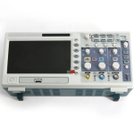
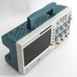
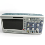
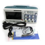
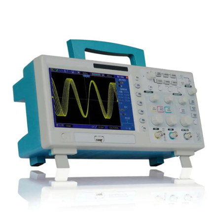
Description
Features
- 200 MHz or 100 MHz or 60 MHz bandwidths
- 1 GSa/s Real Time sample rate
- Large 7 in (17.78 cm) colour display, WVGA (800 x 480)
- Record length up to 2 M
- Trigger mode: edge, pulse width, line selectable video, slop, overtime etc
- USB host and device connectivity, standard
- Multiple automatic measurements
- Four math functions, including FFTs standard
- Provides software for PC real-time analysis
Technical Specifications
| Bandwidth | 200 MHz, 100 MHz, 60 MHz |
| Real-time Sample Rate | 1 GSa/s |
| Equivalent Sample Rate | 25 GSa/s |
| Record Length (Sample Points) | Single-channel: Maximum 2 M; Dual-channel: Maximum 1 M (4 K, 16 K, 40 K optional) |
| SEC or DIV Range | 4 n S or div-40 S/div (in a 2, 4, 8 sequence) |
| Delay Time Accuracy | 500 ps |
| Vertical | |
| A/D Converter | 8-bit resolution, each channel sampled simultaneously |
| VOLTS/DIV Range | 2 mV/div to 5 V/div at input BNC |
| Position Range | ±50 V (5 V/div), ±40 V (2 V/div to 500 mV/div), 2 V (200 mV/div to 50 mV/div) ±400 mV (20 mV/div to 2 mV/div) |
| Rise Time at BNC | ≤1.7 ns, ≤3.5 ns, ≤5.8 ns |
| DC Gain Accuracy | ±4% for Sample or Average acquisition mode, 5 mV/div to 2 mV/div ±3% for Sample or Average acquisition mode, 5 V/div to 10 mV/div |
| Trigger | |
| Trigger Sensitivity (Edge Trigger Type) |
DC: CH 1 or CH 2 (Typical) 1 div from DC to 10 MHz, 1.5 div from 10 MHz to Full EXT (Typical) 200 mV from DC to 40 MHz EXT or 5 (Typical) 1 V from DC to 40 MHz AC: Attenuates signals below 10 Hz HF Reject: Attenuates signals above 80 kHz LF Reject: Attenuates signals below 150 kHz Noise Reject: Reduces trigger sensitivity |
| Trigger Level Range | CH 1, CH 2: ±8 divisions from centre of screen EXT: ±1.2 V EXT or 5: ±6 V |
| Trigger Level Accuracy, typical (Accuracy is for signals having risen and fall times ≥ 20 ns) |
CH 1, CH 2: ± (0.3 div × V/div) (within ± 4 divisions from centre of screen) EXT: ± (6% of setting 40 mV) EXT or 5: ± (6% of setting 200 mV) |
| Holdoff Range | 100 ns to 10 s |
| Trigger Type | |
| Edge | Trigger on the rising or falling edge |
| Pulse Width | Trigger on positive or negative pulses Pulse Width Range: 20 ns to 10 s |
| Video | Trigger on an NTSC, PAL, or SECAM standard video signal Line Range: 1 to 525 (NTSC), 1 to 625 (PAL/SECAM) |
| Slope | Trigger on a positive or negative slope Set Time: 20 ns to 10 s |
| Overtime | from the rising or falling edge Set Time: 20 s to 10 s |
| Alternate | Internal trigger on edge, pulse width, video, or slope |
| Measurement | |
| Cursors | Manual: The difference between voltage cursors ΔV; the difference between time cursors ΔT; 1/ΔT calculated by Hz. Tracing: The voltage and time at a waveform point |
| Automatic | Pk-Pk, Max, Min, Mean, Cyc RMS, Frequency, Period, Rise Time, Fall Time, Positive Width, Negative Width |
| Display | |
| Type | Right angle 7 in (17.78 cm) TFT 16-digit colour LCD |
| Resolution | 800 x 480 dots |
| Contrast | 16 gears, with the progress bar to show adjustment |
| Interface | USB host and USB slave |
| Power Supply | |
| Voltage | 100 V to 120 V AC RMS (±10%), 45 Hz to 440 Hz, CAT II 120 V to 240 V AC RMS (±10%), 45 Hz to 66 Hz, CAT II |
| Power | <30 W |
| Fuse | 2 A, T rating, 250 V |
| Size | 12.32 in x 4.25 in x 5.59 in (313 mm x 108 mm x 142 mm) |
| Weight | 4.58 lb (2.08 kg) (exclusive of packing and accessories) |