Description
Key Features
- TFT true color display and touch screen operation
- Tone generation
- Web browsing
- Windows CE operation system, Graphical interface, easy operation
- Auto-off function to save power
- Audio and LED status indicators
- Software upgradable online
- Auto line-tracking
- Quality of xDSL service verification
- Automatic set up of critical line threshold parameters
Technical Specifications
| xSDL Testing | |
| Attenuation | 0 ~ 63.5 dB |
| Output power | -32.0 dB ~ 31.5 dBm |
| Noise Margin | -64.0 dB~ 63.5 dB |
| ADSL2+ Downstream rate | 0 ~ 24 Mbps |
| ADSL2+ Upstream rate | 0 ~ 1.2 Mbps |
| VDSL2 Downstream rate | 0 ~ 100 Mbps |
| DMM Testing | |
| Loop Resistance | 5Ω ~ 5K Ω ±5 % |
| Capacitance | 0 ~ 500 nF± 10 % |
| DC Voltage | -110 V ~ 110 V ±5 % |
| AC Voltage | 0 ~ 110 V±5 % |
| Insulation Resistance | 0.1 MΩ ~ 50 MΩ ±10 % |
| General | |
| Interface | RJ-11, RJ-45, USB, DC power |
| Display | 2.8” 320 x 240 TFT true color, touch screen |
| Operation Mode | Touch and keyboard |
| Battery | Li-ion battery |
| Charging Time | 3 hours |
| Operation Time | 5 hours |
| Data Storage | 50M (expandable)
More than 2000 records. |
| Size | 7.87 in x 4.72 in x 2.36 in(200 mm x 120 mm x 60 mm) |
| Weight | 35.27 oz (1000 g) |
| Humidity | 5 % to 95 % |
| Operating Temperature | -14 ˚F to 122 ˚F (-10 ˚C to + 50 ˚C) |
| Storage Temperature | -4 ˚F to 158 ˚F (-20 ˚C to + 70 ˚C) |
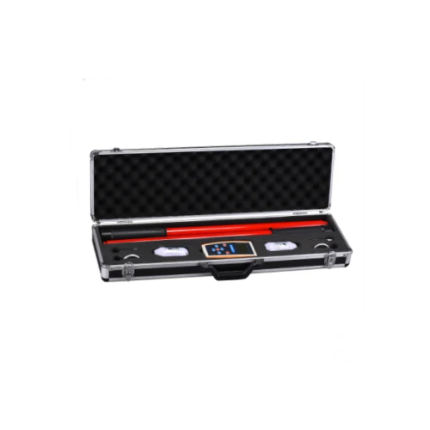
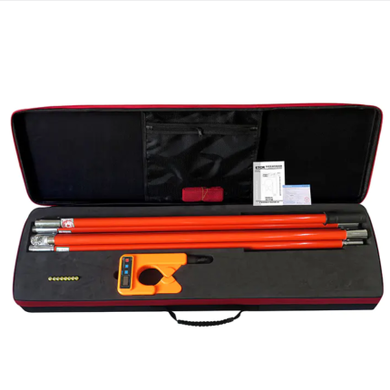
Standard Accessories
The package includes
| Item | Specs | Quantity |
| RJ-11 TO Alligator Clip Cable | 2.0 m | 1 |
| Cross over Cat5 Ethernet Cable | 1.5 m | 1 |
| Stylus | 8.4 V/2.0 A | 1 |
| Power Supply | – | 1 |
| Software Setup CD | – | 1 |
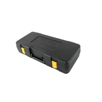
| Waterproof Package | – | 1 |
| User Manual | – | 1 |
Optional Accessories
| Item | Specs | Quantity |
| Tone Generator | TPT-8010 A | – |
| Mouse | USB port | – |
| U Disk | 4G | – |
General Operation and User Notes
General Operation
- Test Interface
Please connect test line to the instruments test interface, please do not touch the bare metal parts of the test nip to prevent electric shock if working with a high voltage circuit.
- USB interface
Please do not short-circuit interface with metal, otherwise the inner circuit will be destroyed.
- Display
Please remove protective film enclosed for before using instrument.
- Cleaning
The instrument cover should be cleaned by soft dry cloth, do not to use volatile chemicals as the plastic may discolor.
- Battery Maintenance
Over an extended period of time if the instrument is left on a low charge, the battery could fully discharge, it is recommended that you fully charge the instrument. If you notice that the battery life has declined you should have the battery replaced.
- Cover and Panel Protection
Please do not sprinkle volatile chemicals on cover or panel, and do not touch Rubber or Polyvinyl Chloride with cover or panel in long time, to prevent malfunctions.
- Instrument Movement
When the instrument should be moved, please ensure that power line and connection cable disconnected with instrument, then take up the instrument. Unplug the cable after using
- Malfunction
If there are abnormal sound, smell or smog, please shut down machine and unplug the power line.
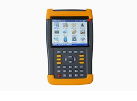
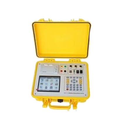
Instrument Front View
Instrument Configuration

Indicator Lights
Includes: Power Ethernet, xDSL LINK, xDSL ACT
Definition of Indicator Lights are as follows:
- Power Indicator Light: constant red light on power up.
- Ethernet Indicator Light: constant green indicates Ethernet link; blinking green light, suggests that Ethernet has data stream.
- xDSL LINK Indicator: slow blinking green – the unit is seeking a xDSL signal; fast blinking green light suggests xDSL LINK protocol; constant green light – xDSL links has been installed.
- xDSL ACT Indicator: Ethernet data stream is present.
Keystroke
Definition for each key are as follows:
- Power Key: with the unit in the on state, press the Power Key for 1 second to suspend the instrument. To complete shut off, please press Power key and hold on for 5 seconds.
- Soft key on-off: in operation interface, press to switch or close soft keyboard.
- Help/ transverse and vertical Screen Switch: To operate WEB Browser, press to switch from transverse and vertical Screen along with system help.
LCD Display
The TFT color LCD Display, is touch screen with lattice 480 × 272.
Instrument Interface
Touch Pen
Touch Pen, an accessory of the instrument used to click on the screen.
Ethernet Interface
RJ-45 interface that complies with Ethernet interface standard, used to connect with Ethernet cable or RJ45 cable plug for Broad Band IP. The Ethernet interface supports auto crossover detection function.
xDSL Interface
xDSL interface is xDSL user line interface and is also the input interface of DMM.
Power Supply Interface
The power input is 50 Hz/60 Hz AC 100 ~240 V, output voltage is 8.4 V DC.
USB Interface
USB interface used for USB Disk and USB mouse.
xDSL and Ethernet Cable
xDSL Test Cord
The instrument connects to an xDSL user line, one end plugs in test jack and other end connects to the tested line. During operation, please do not touch the bare metal of alligator as there may be high voltage on the line.
Ethernet Cable
The configured cable can be connected with IP-PBX or Hub; the instrument can connect with twisted cable, it can connect directly with Ethernet interface of the instrument when it connect with cable of Broad Band IP, indicator light on the interface will work when Ethernet links.
Main Functions and Technical Parameters
xDSL Test
This instrument can emulate Modem + PC function along with comprehensive physical layer tests, network layer test and application layer test of xDSL subscriber line, thus verify the circuit quality.
Physical Layer Test:
ADSL2+:
- Comply with: ITU G.994.1 (G.hs), ITU G.992.5, ITU G.992.5 Annex L, the max connecting distance: 6.5km. ADSL, ADSL2, READSL compatible.
- Test DSL Transmission Parameter:
- DSL upstream channel speed (mixed mode/ Quick Mode): 0~1.2Mbps
- DSL downstream channel speed (mixed mode/ Quick Mode): 0~24 Mbps
- DSL attenuation: 0~63.5 dB
- DSL noise margin: 0~32 dB
- DSL upstream/downstream maximum speed and channel utilization rate
- DSL output power Bits adjusted on DMT sub channel: 0~15, sub channels frequency quantity.
- DSL circuit errors quantity (CRC, HEC, FEC, NCD, OCD)
- Display status on DSL circuit: LOSS, Links failure
- Display DSL circuit link mode
VDSL2:
- Comply with: ITU G.992.3
- Test DSL transmission parameters:
- DSL upstream channel speed: 0~100 Mbp
- DSL downstream channel speed: 0~100 Mbp
- DSL attenuation
- DSL noise margin
- DSL upstream/downstream maximum speed and channel utilization rate
- DSL output power
- Bits adjusted on DMT sub channel: 0~15, sub channels frequency quantity.
- DSL circuit error second FECS, ES, RES, LOSS, UAS
- Display status on DSL circuit: LOSS, Links failure
- Display DSL circuit link mode
Modem Emulation
User can replace, dial-up and link to the internet through the instrument to verify whether there is problem with users Modem.
PPPoE dial-up and modify PPPoE dial-up properties
Simulate subscriber Modem and PC, PPPoE dial-up, verify the connectivity between subscriber and ISP service provider.
Network Layer Test:
Ping, Ipconfig, Route, Router trace, etc.
Application Layer Test:
Web Browse, Network Speed Measurement, FTP Speed Measurement.
LAN Test
This instrument can perform a LAN or Broad Band PPPoE dial-up test, LAN network layer test and application test.
LAN Tests includes the following functions:
- DHCP subscriber end test
- PPPoE dial-up and modify PPPoE dial-up properties, verify if there is trouble in Broad Band IP or LAN.
- Network Layer Test: Ping, Ipconfig, Route, Router trace, etc.
- Application Layer Test: Web Browse, Network Speed Measurement, FTP Speed Measurement, etc.
DMM and Cable Test
DMM Test
Test the AC/DC, Circuit loop resistance, Circuit capacitance, Circuit insulation.
DMM test parameters as follows:
| Item Range | Unit | Test | Relative error |
| Voltage Test | V | 0—110 DC | ±5 % ±2 V |
| V | 0—110 AC | ±5% ±2V | |
| Loop Resistance Test | Ω | 0—10 | ±2Ω |
| 10—5000 | ±5 % | ||
| Capacitance Test | nF | 0—10 | ±2 nF |
| 10—500 | ±10 % | ||
| Insulation Test | MΩ | 0—1.0 | ±0.1 MΩ |
| 1.0—50 | ±10 % ±0.5 MΩ |
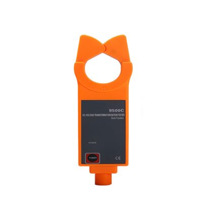
Tone Generator
Send an audio signal at one end of the twisted pair while using an optional tone tracer device to find the corresponding pair at the other end.
MODEM Emulation
Completely replace user’s Modem, subscriber can use this device as “Golden” Modem to dial-up and surf website to verify if the trouble is the user’s Modem.
OPERATION
- Power ON: To turn on the unit press the Power key.
- Normal Power Off: Click the Shutdown key or press the power key, a window will emerge and ask whether you would like to shut down, then confirm to shut off.
- Forced Power Off: When the instrument cannot be shut down by system window or shutdown key, shut down by holding key for greater than 5 seconds.
LCD Display Interface
- On power up, the instrument enters the main screen which includes 3 parts:
- Status Indicator bar
- Functions bar
- Tool bar

Status Indicator Bar
The bar includes time indicator, battery capacitance indicator, and return Indicator and U discs indicator.
Functions Icon Bar
This bar includes a series of icons, each represents a function, press the icon and enter the functions interface
XDSL TEST
Functional Introduction:
The Handheld xDSL Tester tests xDSL lines and verifies dial-up service through a built-in “Golden” Modem. As an integrated test, it includes physical layer test, parameter settings, PPPoE properties, PPPoE dial-up, network layer test, Web Browse, ATM loopback test, Network Speed Measurement, FTP Speed Measurement, etc. It can emulate end user equipment to achieve PPPoE dial-up, network layer test and Web Browser, then acquire physical layer parameters of the line link and verify line quality.
This function is helpful to verify the subscriber line and solve problems resulted from Modems and PC.
How to Use:
Connect the xDSL pair directly into the RJ11 port of the instrument or connect to an xDSL
Splitter, then press icon to enter the xDSL test window, as follow

xDSL test function includes: physical layer test, DSL parameter settings, Modem emulation, PPPoE properties, PPPoE dial-up, ATM loopback test, network layer test, Web Browse, Network Speed Measurement, FTP Speed Measurement, etc.
If you want to test whether the built-in Modem connects with xDSL station equipment, settings are not required. If connected, the instrument indicator light is on, click to enter to check the physical layer parameters.
To test whether xDSL can log onto a website, please do the following: set Modem parameter (VPI/VCI) →set PPPoE properties (can be skipped) →PPPoE dial-up, when the xDSL LINK light is on, click PPPoE dial-up, (required to input user name/ password), then Web Browse.
Network Layer Test
Functions Introduction:
After PPPoE dial-up link through the built-in xDSL Modem, perform a Ping, Ipconfig, Tracer, and Route Test of the Network Layer.
How to Use:
Click Network Layer test icon to enter Network Layer test window as follows:

LAN TEST.
Functions Introduction:
Tests for when connected to the Ethernet and broadband IP user network. The device can verify the DSL web utility when emulates a computer connection to DSL Modem and PPPoE dial for web browsing, it also can connect to an Ethernet as an IP terminal for the test of DHCP client end, PPPoE dial and web browser, for verifying the Ethernet utility.
How to Use:
Click LAN test icon access to LAN test options as below displayed.

CABLE TEST
Functions Introduction:
Built-in full functional auto range digital power meter used for testing the telephone line physical characteristic, audio-tracking function can search for the matched wire pair.
How to Use:
Click cable test icon that will access to window below:

Constant Voltage Test
The circuit can be tested for constant DC voltage. This tests helps identify opens or no voltage across pair.
This test is a DC voltage test and the range is -110 V ~ +110 V, when the reading is beyond this value the device will prompt “Test overload”
AC Voltage Test
The AC Voltage tests 0-110 V AC for AC voltages across test pair, care should be taken to prevent electrical shock. When beyond 110 V value the device will prompt “Test overload”.
Loop Resistance Test
The length of line can be tested by loop resistance. Otherwise, if the cable length is given, the cable connection will be tested by loop resistance.
The formula for cable length loop resistance value is
L=RL/RO (Km)
In above formula, RL is loop resistance test value (unit: Ω), RO is loop resistance per kilometer (unit: Ω)
In general condition 0.32 mm copper line RO=435.2Ω, 0.4 mm copper line RO=278.5Ω, 0.5 mm copper line RO=178.3Ω.
If the device prompts “Test Overload” it means that the test clap is disconnected or the test line has not been connected, please check test claps and verify the test circuit is connected to the line and test once again.
During the test when line voltage is over 5V, the device will prompt “Line-voltage”, at this moment the loop resistance test is unavailable, the test will only performed when there is no voltage on the line.
Capacitance Test
The line length can be measured by capacitance test. When there is no bridged tap and the cable is not in water, the length can be measured by test electric capacitance, the formula is
L=Cab/CO (Km).
In above formula, Cab is electric capacitance test value (unit: nF), CO is electric capacity value per kilometer (unit: nF).
The capacitance of the cable in commonly used cable is CO=51nF
When the device prompts “Test Overload” that means the capacitance is overload or cable default, retest it after check the cable.
During the test when line voltage is over 5V, device will prompt “Line-voltage”, at this moment the capacitance test is unavailable, and the test can only be performed when there is no voltage on the line.
CHARGING THE INSTRUMENT
This device uses an internal 7.4 V 4000 mAh Li battery. When the battery sign indicates a low battery, the device prompts no battery and shuts down automatically. Charge immediately. Li battery can be charged at any time and has no memory effect. We advise you to charge the battery, when charge is low. To charge: shut down the device and then connect the charger to the AC socket, note the charge indicator light is green, then plug into the test set and the indicator light turns red indicating the test set is charging When the indicator light turns green the battery is fully charged, the charger can removed.
BATTERY REPLACEMENT
The 7.4V 4000 mAh battery is field replaceable and GAOTek highly recommends a factory trained technician replace the battery to prevent damage or void warranty.
MALFUNCTION ANALYSIS AND SOLUTION
| Problems | Reasons Analysis | Solutions |
| Device power on disabled | Low battery | Charge unit and then try again |
| When device is in the xDSL the build-in Modem activation in the ADSL line disabled. | 1.The line
2. No signal, test if the line has 48V voltage by DMM voltage test. |
1. Confirm if the line is connected. 2. If no voltage indicated, the line has no open service |
| After a short time xDSL test, indicate low battery. | Because the built-in Modem has large power consumption, the power cannot supply enough power for xDSL test | Use AC adapter xDSL test |
| Disable to identify U disk when properly connected | The device cannot read all U discs. | Unplug and try again, if it does not work try another U disk. |
| PPPoE dia does not work but there is activation | Please confirm the correct user name and password, VPI/VCI also the PPPoE properties setup. | Modify the PPPoE properties according to the line requirement, and input the correct password for PPPoE dial. |
| Web browsing disabled | Be PPPoE dial is done. | Be sure the PPPoE dial is correct, or try another website |
| Ethernet indicator light disabled when Ethernet cable is connected to device | Network cable divided into crossover cable and Ethernet cable | Connect to other Ethernet port if one Ethernet port cannot be identified |