Description
Overview
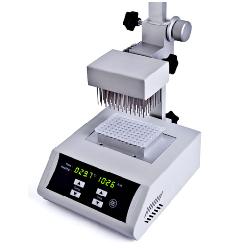
GAOTek 96-Gas-Needles Nitrogen Concentrator (High Temp. Accuracy) is mainly used for concentrating or preparing samples, required for drug screening, hormone analysis, liquid phase, and mass spectrometry, in batch, with high temperature accuracy. It works by blowing nitrogen in the surface of sample which is being heated to accelerate evaporating and separating the solvent in the samples without oxygen. Instead of the rotary evaporation instrument, nitrogen sample concentrator can efficiently concentrator dozens of samples simultaneously. This device has ease of operation and is simple and convenient to use because of the LED display, temperature and time diminishing display.
Key Features
- Synchronous working with heating by dry bath in the bottom and nitrogen blowing on the surface accelerates liquid evaporation and sample concentration
- The height of the air cavity can be adjusted. The length of a standard gas needle is 3.14 in (80 mm)
- Gas needle is controlled independently. Separate blow of each needle and flow regulating of each needle are available to avoid gas wastage
- The entire system can be arranged in the ventilation cabinet when processing concentration of toxic solvents
- Built in overheat protection, automatic fault detection and fault beep alarm devices
- LED display, immediate temperature and diminishing time display. Operation is simple and convenient.
- Standard configured air cavity and adjustable bracket
Technical Specifications
| Temperature Range | R.T. 41 °F~302 °F (+5 °C~150 °C) |
| Heating Time | ≤30 min; 104 °F to 302 °F (40 °C to 150 °C) |
| Temperature Accuracy
104 °F~212 °F (40 °C ~100 °C) |
±32. 9 °F (±0.5 °C) |
| Temperature Accuracy
212 °F~302 °F (100 °C ~150 °C) |
33.8 °F (±1 °C) |
| Temperature Uniformity 212 °F (100 °C) | ±32. 9 °F (±0.5 °C) |
| Blocks Quantity | 1 block |
| Temperature Display Accuracy | 32.18 °F (0.1 °C) |
| Time Range | 99 h 59 min |
| Nitrogen Flow Rate | 0 L/min~10 L/min |
| Nitrogen Pressure | ≤0.1 MPa |
| Power | 200 W |
| Dimensions | 10.23 in × 8.66 in × 19.68 (260 mm × 220 mm × 500 mm) |
| Working Conditions | |
| Room Temperature | 41 °F to 86 °F (5 °C to 30 °C) |
| Relative Humidity | ≤70 % |
| Usable Power | AC 220 V~ 50 Hz-60 Hz |
Additional Information
Conventional configuration
2 types of optional blocks are supplied – Block A and Block B. Block can be interchanged easily.
| Type | Description | Block Dimension |
| Block A | 0.2 ml centrifugal tube × 96 | 3.07 in × 4.48 in × 1.02 in (78 mm × 114 mm × 26 mm) |
| Block B | 96-well enzyme plate (no hole) | 3.18 in × 4.84 in × 0.74 in (81 mm × 123 mm × 19 mm) |
Structure Description


Instrument Installation

Installation steps:
- Put the main instrument on the horizontal and stable bench.
- Fully insert the upright into the post permanent seat behind the main instrument. Screw the pillar fixed screw knob to tighten the upright.
- Screw the mobile base fixed knob into the left screw hole of the mobile base. Hold the knob of mobile base and counter clockwise or clockwise rotate the mobile seat regulation handle to adjust the mobile base position. Use the mobile base fixed knob to tight the mobile base.
Note: When moving the mobile base, two hands must be used in conjunction with operating mobile base fixed knob and mobile seat regulation handle.
- Insert the chamber insert port of the air chamber in to the chamber positioning, fully insert column of gas chamber, screw gas chamber fixed knob to tight the air chamber.
Gas needle installation
The air cavity is standard positing the 96 gas hold as 0.47 in × 0.31 in (12 mm × 8 mm). Refer to below chart.


- Insert the gas needle into the air chamber (the gas needle goes through 2 layers of hole pad, seal pad to the air chamber). If there are extra holes, do not insert any needle to avoid gas waste. The seal pad is auto-airtightness, get out of the needle, the hole will not leak air.
Note: Bleed pressure should be no more than 0.05 Mpa.
- After the needle assembly is finished, fix the air chamber to the mobile base.
- Fast connect function is built at the gas connector for convenient and quick connect and shut off the air.
Operation:
Compress the connector and push it towards air-in port. The spring in the connector will auto clamp air-in port. To detach the gas tube, please compress the connector and push. The spring in the connector will auto break away from air-in port.
- Air-in Port
- Connector
- Gas Tube
- Loosen the knob and turn the mobile seat regulation handle till the gas needle is inserted into the top of the test tube about 0.39 in (10 mm) above the fluid. Then fix and tighten mobile base.
- Turning on the gas source when needed.
Notice: The gas pressure should not be more than 0.05 Mpa. Heavy pressure would make the gas chamber seal bad and leakage will lead to waste of the gas source.
Gas Control Valve Installation
Gas Control Valve Structure

Push out the Pressure Control Knob, clockwise turn it to enhance the pressure, and counterclockwise turn it to weaken the pressure. Press the Pressure Control Knob to fix the pressure (pressure cannot be adjusted under this situation).
Counterclockwise turn the Gas Control Knob to increase the flow rate, and clockwise turn the Gas Control Knob to decrease the pressure till shut off the gas flow.
Notice: The Gas Control Valve is accessory for purchasing separately according to user’s demands.
Gas Control Valve Installation

Refer to the above figure.
Connect the Air-out Port of the Gas Control Valve and Air Connection of the sample concentration with a tube (length is around 59.05 in (1.5 m)).
Connect the air-out port of the nitrogen gas cylinder and Air-in Port of the Gas Control Valve with a tube (length is around 118.2 in (3 m)).
Notice: Slowly turn on the nitrogen gas cylinder. Make the air pressure between 0.1 MPa and 0.2 Mpa. Then open the pressure control knob of the Gas Control Valve to slowly adjust the pressure around 0.02 MPa (value indicated by the Pressure Indicator Meter). Actual pressure is better controlled between 0.02 MPa and 0.05 MPa according to the needed needle quantity.
Operation Panel

START/STOP Run/stop button: start operation when the button is pressed after setting the temperature and the time value. Press this button for 2 seconds to stop the instrument in operation.
![]() Decreasing button: decreases the value set
Decreasing button: decreases the value set
![]() Increasing button: increase the value set
Increasing button: increase the value set
START/STOP Run/stop button: start operation when the button is pressed after setting the temperature and the time value. Press this button for 2 seconds to stop the instrument in operation.
Operation Guide
Temperature and time setting
- Power on, the LED displays as shown below. The instrument enters the initial state with a sound.

- Two seconds later, the value changes to block current temperature and setting time of last operation. As below figure shows, “28.5” is the block current temperature, and “00:35” is the last setting time which means 35 minutes.

- Click
 or
or  of , the temperature value changes to the setting value in last operation, and the last digit of the setting value flickers. Press or of to change the temperature setting value. Keeping these buttons pressed will lead to the value changing speed tens, hundreds, or thousands times fast. When the value reaches the target, release or , the instrument automatically confirms and saves the value.
 - Click
 or
or  of , the last digit of the time setting value flickers. Press
 or
or  of to change the time setting value. Keeping these buttons pressed will lead to the value changing speed tens, hundreds, or thousands times fast. When the value reaches the target, release or , the instrument automatically confirms and saves the value.
 - Note: The time setting “00:00” means no the operation timing, the instrument runs continuously at the setting temperature.Start and stop: After accomplishment of temperature and time setting, click the Start/Stop key to start.
 Press
Press or
or  to reset the temperature and time, then, press start/stop to start a new operation. Press start/stop without any change of the settings to restart the operation. When the instrument is heating, the dot “.” of the temperature value flickers regularly. When the temperature reaches the setting value, the dot “.” stops flicker, and the colon “ : ” of the time value begin to flicker, meanwhile, the time is in the countdown.When the operation completes, the instrument goes to waiting interface. Press
  or
or  to reset the temperature and time, then, press start/stop to start a new operation. Press start/stop without any change of the setting to restart the operation.Continuously press start/stop for 2 seconds during the operation to stop running. Press start/stop again to continue the operation.
- Temperature calibration The temperature of the Instrument has been adjusted before it is sold out. In case there is deviation between the actual temperature and the displayed temperature, you can do as follow for temperature calibration.NOTICE: The instrument has 2 calibration temperature points to ensure the veracity. It is linearly adjusted on 104 °F (40 °C) and 212 °F (100 °C). The temperature accuracy will be within ±32.9 °F (±0.5 °C) after temperature calibration.Both the environmental and the block temperature should be lower than 95 °F (35 °C) when calibrating. Adjustment Methods:
The instrument has 2 calibration temperature points to ensure the veracity. It is linearly adjusted on 104 °F (40 °C) and 212 °F (100 °C). The temperature accuracy will be within ±32.9 °F (±0.5 °C) after temperature calibration.Both the environmental and the block temperature should be lower than 95 °F (35 °C) when calibrating.When the operation completes, the instrument goes to waiting interface.
- Power on the instrument, it enters into waiting interface. Make sure the current temperature in display is below 95 °F (35 °C). If the temperature is higher than 95 °F (35 °C), please wait until it is down below 95 °F (35 °C).
- Inject olefin oil into one of block well, and then put a thermometer into this well (the precision of the thermometer should be 32.18 °F (0.1 °C) and the temperature ball should be absolutely immersed into the olefin oil in the block well). Adiabatic material is needed on the block to separate from circumstance.

NOTICE: To ensure the calibration precision, read the actual temperature value after the temperature reaches calibration points for at least 20 minutes.
3. Press ![]() or
or ![]() and simultaneously to enter the temperature calibration interface. LED displays “
and simultaneously to enter the temperature calibration interface. LED displays “![]() ” in the time display, the temperature displays the current temperature and the program auto controls the temperature to 104 °F (40 °C). When the temperature reaches 104 °F (40 °C), the decimal digit begins to flicker. Wait for at least 20 minutes, the actual temperature of thermometer is 103.28 °F (39.6 °C),
” in the time display, the temperature displays the current temperature and the program auto controls the temperature to 104 °F (40 °C). When the temperature reaches 104 °F (40 °C), the decimal digit begins to flicker. Wait for at least 20 minutes, the actual temperature of thermometer is 103.28 °F (39.6 °C),
4. Press  or
or of temperature to amend the temperature value to 103.28 °F (39.6 °C). Press “Start/Stop” to confirm.
Program saves the value.
Temperature rises to 212 °F (100 °C) automatically. 212 °F (100 °C), the decimal digit begins to flicker. Wait for at least 20 minutes, the actual temperature of thermometer is 214.7 °(101.5 °C), press ![]() or
or ![]() of temperature to amend the temperature value to 214.7 °F (101.5 °C). Press “Start/Stop to confirm. After the temperatures have been adjusted, press and simultaneously to exit the temperature calibration and return to waiting interface. Press
of temperature to amend the temperature value to 214.7 °F (101.5 °C). Press “Start/Stop to confirm. After the temperatures have been adjusted, press and simultaneously to exit the temperature calibration and return to waiting interface. Press 
 and simultaneously during the calibration to exit the adjustment procedure, the calibration is invalid.
The exchange of the metal block
- Pull out the two screws which fix the block to the heating board with the screwdriver.

2. Fix the raiser in the center well of the block and pull out the raiser with the block.
Screw the raiser out from the block, then fix the raiser to another block needed.

3. Put the block in the instrument and fix it with screws.

Notice: It is a little complicated to exchange the block, please be a bit patient.
Exchange the seal pad of the Air chamber

- When obvious air leakage happens, please exchange the seal pad in the air chamber.
- Loosen the air chamber screw, unplug the fast connector to take down and overturn the air chamber to a bench top.
- Loosen the 4 screws on the hole pad to fetch the hole pad and seal pad.
- Well put in a new seal pad and hole pad. Make sure the 2 pads are put plat and in place.
- Wrest the 4 screws in opposite angles turn to fix the air chamber uniformly.
- Overturn the air chamber. Put the air chamber back to the sample concentration main instrument.
Error Analysis and Trouble Shooting
| No. | Fault phenomenon | Cause analysis | Recovery processing |
| 1 | No signal on the display when power on | No power | Check the connection of power |
| Broken fuse | Exchange fuse (250 V 4 A Ф5×20) | ||
| Broken switch | Exchange the switch | ||
| Others | Contact the seller | ||
| 2 | The actual and display temperature are quite different | Broken sensor or loose contact of the block | Contact the seller |
| 3 | “ERR” in the display with the alarm of “du…” | Broken sensor or room temperature below zero. | Contact the seller |
| 4 | No heating of the block | Broken sensor. | Contact the seller |
| Solid state relay damage | |||
| Broken heater | |||
| 5 | Key invalid | Key broken | Contact the seller |


