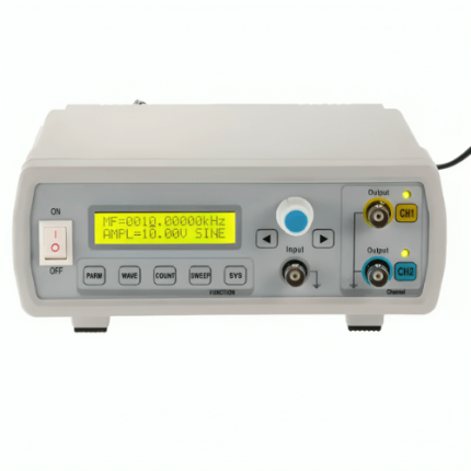
| Frequency |
LW-1641 0.1 Hz to 2 MHz, LW-1642 0.1 Hz to 5 MHz, LW-1643 0.1 Hz to 10 MHz |
| Frequency Range |
60 MHz |
| Waveforms |
Square |
| Sampling Rate |
100 MSa or s |
| Impedance |
50 ohms |
| Wave Form Vertical Resolution |
8 bits |
| Output Signal |
0 V to 10 V |
| Output Impedance |
50 ohms ±10% |
| Amplitude |
Not less than 20vp-p (no load) |
| DC Voltage |
0 V to ±10 V, continuously adjustable |
| Symmetrical Range |
90 10 to 10 90 |
| Square Wave Front |
LW-1641 <100ns, LW-1642 <50ns, LW-1643 <35ns |
| Sine Wave Characteristics Distortion |
Less than 1% (10 Hz to 100 kHz) |
| Sine Wave Characteristics Frequency Response |
0.1 Hz to 100 KHz No more than ±0.5 dB, 100 KHz to 5 MHz (LW-1642) No more than ±1 dB, 100 KHz to 2 MHz (LW-1641) No more than ±1 dB |
| TTL Or CMOS Output Level |
The low level of TTL pulse is not more than 0.4 V, the high level is not less than 3.5 V, the low level of CMOS pulse wave is not more than 0.5 V, and the high level is continuously adjustable from 5 V |
| TTL Or CMOS Output Rising Time |
LW-1641 <100ns, LW-1642 <100ns, LW-1643 <100ns |
| VCR Input Voltage |
-5 V to 0 V ±10 |
| VCR Input Maximum Voltage Control Ratio |
1000 1 |
| VCR Input Output Signal |
DC-1 KHz |
| Frequency Meter Test Scope |
1 Hz to 1 KHz≥10 vp-p |
| Frequency Meter Input Impedance |
Not less than 3.28084 ft (1 m) ohms or 20f |
| Frequency Meter Sensitivity |
100 mVrms |
| Frequency Meter Maximum Input |
150 V(AC +DC) |
| Frequency Meter Input Failure |
20 dB |
| Frequency Meter Accuracy |
Less than 0.003% ±1 word |
| Frequency Meter Power Supply |
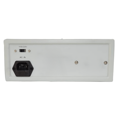
220 V or 110 V ±10% 50 Hz or 60 Hz |
| Size |
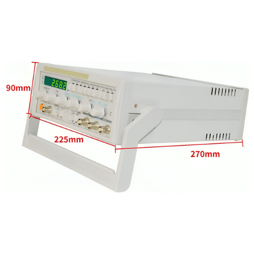
10.6299 in × 8.85827 in × 3.54331 in (270 mm × 225 mm × 90 mm) |
| Weight |
6.61387 lb (3 kg) |

