Description
Overview
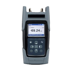
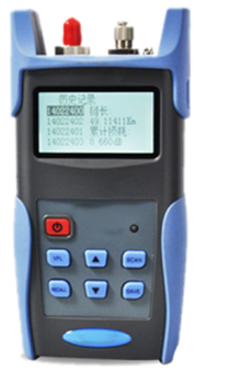
GAOTek Fiber Loss Tester can generate multiple wavelengths for testing and it can measure the optical power of different wavelengths. With the function of wavelength auto-detection, the tester actualizes the auto test, which improves the test efficiency greatly and lowers the error a lot during the test. It is a powerful and reliable tool for the daily maintenance of the telecom workers. Wavelengths of 3.35 x 10 -5 in (850 nm), 5.12 x 10 -5 in (1300 nm), 5.16 x 10 -5 in (1310 nm), 5.87 x 10 -5 in (1490 nm), 6.10 x 10 -5 in (1550 nm), and 6.40 x 10 -5 in (1625 nm) are already configured in the tester for the convenience of the user.
Features
- Measurement range of -70 to 10 (PM-1) and -50 to 27 (PM-2) meets the testing requirement in the telecom field.
- Built-in VFL (2.56 x 10 -5 in (650 nm)) provides strong complement for the dead zone testing with an OTDR and fusion light-pass testing with Fusion Slice.
- Measure the length of the fiber according to the loss in the fiber.
- Large storage capability of more than 1000 test results.
- Connecting with PC via USB interface for data uploading, optical power calibration and threshold modifying with the help of GAO Test Console software.
- Small size, light weight, multifunctional and portable.
- 260 k true color LCD display which displays full test details of wavelength, modulated signal and power state.
- It supports both AC and battery power supply (continuous supply for 30 hours).
- High-quality protection jacket for protection, vibration and dropping.
Technical Specifications
| Wavelength Ranges | 3.15 x 10 -5 in to 6.69 x 10 -5 in (800 nm to 1700 nm) | ||
| Calibrated Wavelengths | 3.35 x 10 -5 in (850 nm), 5.12 x 10 -5 in (1300 nm), 5.16 x 10 -5 in (1310 nm), 5.87 x 10 -5 in (1490 nm), 6.10 x 10 -5 in (1550 nm), 6.40 x 10 -5 in (1625 nm) | ||
| Measurement Ranges | PM-1 | -70 to 10 dBm | |
| PM-1 | -50 to 27 dBm | ||
| Accuracy | ±0.25 dB±5% | ||
| Unit | dBm /dB/w ( nw, uw) | ||
| Resolution | 0.01 dB | ||
| Test Mode | Absolute and Relative | ||
| Auto-identify Wavelength | Yes | ||
| Modulated Signal Identification | 270 Hz,
1 kHz, 2 kHz |
||
| Battery Working Time | >30 hours | ||
| Connector Type | FC/SC/ST Interchangeable | ||
| Light Source | LS-1 | 5.12 x 10 -5 in /6.10 x 10 -5 in
(1310 nm /1550 nm) |
|
| LS-2 | 5.16 x 10 -5 in/6.10 x 10 -5 in /
6.40 x 10 -5 in (1310 nm /1550 nm /1625 nm) |
||
| LS-3 | 5.16 x 10 -5 /5.87 x 10 -5 /
6.10 x 10 -5 in (1310 nm /1490 nm/1550 nm) |
||
| Emitter Type | FP-LD | ||
| Spectral Width | ≤ 1.97 x 10 -7 in (5 nm) | ||
| Output Power | ≥-3.5 dBm | ||
| Output Stability | ±0.05 dB/15 min; ±0.15 dB/8 h | ||
| Auto-identify Wavelength | Yes | ||
| Output Mode | 270 Hz, 1 kHz, 2 kHz | ||
| Connector Type | FC/SC/ST Interchangeable | ||
| VFL | |||
| Wavelength | 650±20 nm | ||
| Emitter Type | FP-LD | ||
| Modulated Frequency | Modulated Frequency | ||
| Other | |||
| Power Supply | Charger | Input | 100~240 V AC |
| Output | 8.4 V DC /1.2 A | ||
| Battery | Lithium Built, Rechargeable | ||
| GAO Test Console Software | Supported by WIN2000/ME/XP | ||
| Operating Temperature | 32 oF to 122 oF (0 ℃ to 50 ℃) | ||
| Storage Temperature | -22 oF to 158 oF (-30 ℃ to 70 ℃) | ||
| Humidity | 5% to 95% non-condensing | ||
| Dimensions (LxWxH) | 7.6 in x 3.7 in x 1.7 in (192 mm×94 mm×43 mm) | ||
| Weight (including batteries) | 0.9 lb (0.42 kg) | ||
Additional Information
Product Compositions
The Fiber Loss Tester consists of following modules:
- Hardware: Main board.
- Software: The Embedded software, surveillance and management PC software “TestManagerPro”.
- Accessories: Waterproof Package, USB Communication Cable, AC Charger, Rechargeable Batteries and Universal Adapter.
Compositions of Instrument
- Front panel: LCD display, OPM, AUTO and VFL LED indicators, keypad
- Back panel: 2 disassembly-proof label, S/N Tag, battery house (showed the Li-ion battery after loosening the screws).
- Front end: Light source output, VFL (Option), Power Meter Input (universal adapter of FC/ SC/ ST, single mode, PC).
- Left end: Mini USB interface
- Right end: 8.4 V DC Input Jack.
Appearance of Product
Power Supply- This instrument can be powered by external power supply or built-in rechargeable batteries.
• External Power Supply
The external power supply requires a power source of 110 V to 240 V AC at a frequency between 50 Hz to 60 Hz (nominal). And the instrument requires a nominal DC supply of 8.4 V. And the instrument can be powered by the external power supply via the AC adapter.
• Rechargeable Batteries
The instrument uses rechargeable battery and the standard is especially defined with 1200 mAh Li-ion battery with output of DC7.4 V.
Replacement of Rechargeable Battery:
A new rechargeable battery can be charged and discharged for about 500~800 times before it cannot be used any more. Normally the fully charged batteries could support the instrument continuous 15 hours working depending upon the test settings. So when the operating duration of the battery is apparently reduced, the batteries should be replaced.
Power Management
This instrument provides automatic power-off function. When the instrument is not under test-started status and there is no keystroke in 5 minutes, this instrument will be turned off automatically. This function can effectively prevent the instrument from being accidentally turned on and the battery from being exhausted during the transport. This function can be set to ON/OFF and duration in “Menu”. The LCD backlight can be shift ON/OFF by pressing the “Backlight”.
Switch-On
Switch-on Inspection Steps
This instrument can be switched on after “Power” key has been pressed for 1 second. After switching-on, the LCD will display the name of product and the embedded software version information. After about 1 second later it beeps, the switch-on process is completed and it enters “Result“ menu.
Setting Time & Date
At the right side of battery indication on the screen, LCD displays the current time in the format of “Hour: Minute”, with 24-hour system. Since the test result is time-stamped, it is necessary to set the right time and date before using the instrument. Time and date can be set in “Time & Date” in the “Menu” interface, by following operational steps:
Press the “Menu” to switch to the “Menu” interface, select “Time & Date”.
Press “OK” to enter the setting menu, and then the date and time of the instrument can be set.
Press “OK” again after the setting is done, and then the instrument will work with the newly-set time.
External Power Requirements
Please use the supplied AC adapter when operating with the instrument or charging the battery. Here are the specs of the AC adapter:
AC Input : 100 V~240 V, 50/60 Hz, 0.35A.
DC Output: 8.4 V, 1200 mA.
Operational Requirements
The tested interfaces are located at the top of the instrument. Before connecting, note the Warning and Caution information given. The instrument contains components sensitive to electrostatic discharge. To prevent component damage, carefully follow the handling precautions presented below.
The smallest static voltage most people can feel is about 3500 volts. It takes less than one tenth of that (about 300 volts) to destroy or severely damage static sensitive circuits. Often, static damage does not immediately cause a malfunction but significantly reduce the component’s life. Adhering to the following precautions will reduce the risk of static discharge damage.
Handling the instrument by its cover. Avoid touching any components or edge connectors.
Accessories
| Fiber Loss Tester | 1 set |
| Charger | 1 pc |
| FC/SC/ST Interchangeable Connector | 2 pcs |
| USB Communication Cable | 1 pc |
| Li-ion Rechargeable Battery (Built-in) | 1 pc |
| Cleaning Cotton Bud | 1 pc |
| Waterproof Package | 1 pc |
| GAO Test Console Setup CD (User Manual) | 1 pc |
| User Guide | 1 pc |
| Quality Certificate Card | 1 pc |
| Maintenance Card | 1 pc |
| Packing List | 1 pc |


