Description
Features
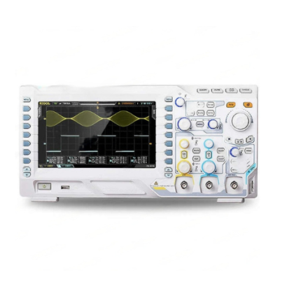
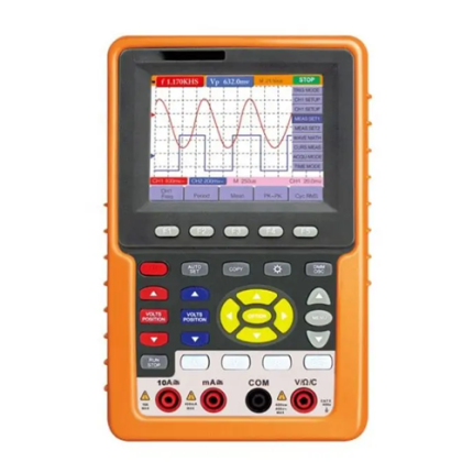
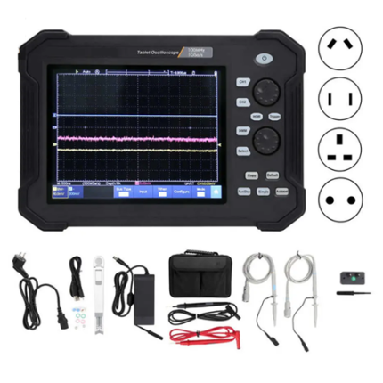
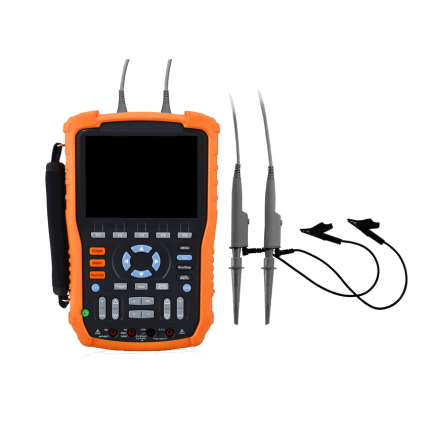
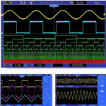
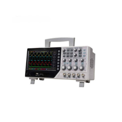
- 16 channels logic analyzer + 2 channels oscilloscope + external trigger
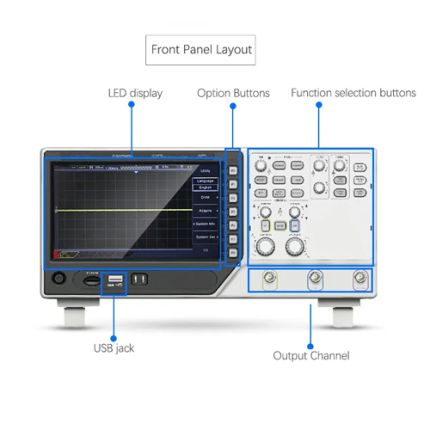
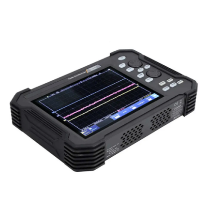
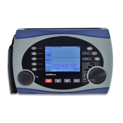
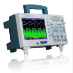
- Big and clear display (7.0 in colour LCD, high revolution 800 x 480), clear lifelike waveform display
- 1 GS/s real time sampling rate
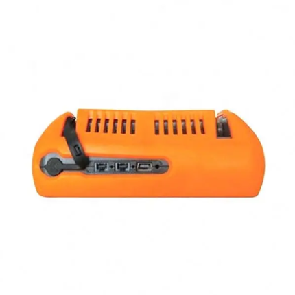
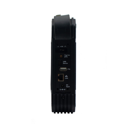
- USB host, support flash memory card storage and USB interface system upgrade
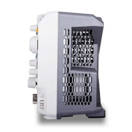
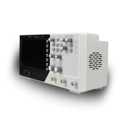
- Ultrathin design, handy volume, easily portable
- 60 MHz Bandwidth
- Each channel record length up to 1 M
- Real time sampling rate up to 1 GS/s
- Powerful trigger function
- 32 kinds of automatic measurement function
- 16 channels divided into 2 groups which is able to setup threshold level individually
- Real time sampling rate up to 500 MS/s
- Powerful trigger function: edge, duration, pulse width, code-type, queen, repeat
Technical Specifications
| Bandwidth | 200 MHz |
| Sampling Rate Range | Max. 1 GS/s |
| Waveform Interpolation | (sin x) /x |
| Memory Depth | Single-channel: maximum 1 M; Dual-channel: maximum 512 K (4 K, 16 K, 40 K optional) |
| SEC or DIV Range | 2 ns/div to 40 s/div |
| Sampling Rate and Delay Time Accuracy | ± 50 ppm over any ≥ 1 ms time interval |
| Delta Time Measurement Accuracy (full bandwidth) | Single-shot, Normal mode: ± (1 sample interval + 100 ppm × reading + 0.6 ns)
16 times above average (1 sampling interval + 100 ppm × readings + 0.4 ns) Sampling interval = SEC or DIV ÷ 200 |
| A or D Converter | 8-bit resolution, each channel sampled simultaneously |
| VOLTS or DIV Range | 2 mV/div to 5 V/div at input BNC |
| Position Range | ± 400 mV (2 mV/div to 20 mV/div)
± 2 V (50 mV/div to 200 mV/div) ± 4 V (500 mV/div to 2 V/div) ± 50 V (5 V/div) |
| Bandwidth Limit (typical) | 20 MHz |
| Low Frequency Response | ≤ 10 Hz at output BNC (-3 dB) |
| Rising Time | ≤ 1.8 ns |
| Vertical Gain Accuracy | 3 % for sample or average acquisition mode, 5 V/div to 10 mV/div 4 % for sample or average acquisition mode, 5 mV/div to 2 mV/div |
| Trigger Types | Edge, Video, Pulse, Slope, Over time, Alternative, Code-type, Duration, Queue, Repeat |
| Trigger Source | CH 1, CH 2, EXT, EXT/5, AC Line |
| Input Coupling | DC, AC or GND |
| Input Impedance, DC Coupling | 1 MΩ 2 % for 20 pF3 pF |
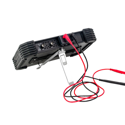
| Probe Attenuation | 1 X, 10 X |
| Support Probe Attenuation Coefficients | 1 X, 10 X, 100 X, 1000 X |
| Math | +, -, x, ÷, FFT |
| Cursors Measurement | Voltage difference between cursors: delt V Time difference between cursors: delt T Reciprocal of delt T in Hertz (1/ delt T) |
| Automatic Measurements | Frequency, Period, Mean, Peak-to-peak, Cycle RMS, Minimum, Maximum, Rise Time, Fall Time, Positive Width, Negative Width |
| Logic Analyzer Specification | |
| Sampled Channels | 16 (divided into 2 groups) |
| Max. Input Impedance | 200 K (C = 10 p) |
| Input Voltage Range | -60 V to 60 V |
| Logic Threshold Range | -8 V to 8 V |
| Max. Sample Rate | 500 MHz |
| Compatible Input | TTL, CMOS, ECL |
| Sample Depth | 512 KSample |
| Cursors | The difference between voltage cursors V; The difference between time cursors T; 1/T calculated by Hz. |
| Measurement | Period and Frequency |
| General Specification | |
| Display | 7 in TFT 16 K Colour LCD, 800 x 480 pixels |
| Dimension | 12.32 in x 5.59 in x 4.25 in (313 mm x 142 mm x 108 mm) |
| Weight | 4.58 lb (2.08 kg) (Not including the weight of package and accessories) |