Description
Overview
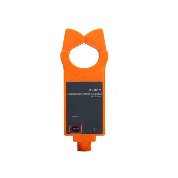
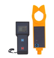
GAOTek High Voltage Current Ratio Tester with Clamp Ammeter breaks through the traditional structure, specializing in on-line measurement of high-voltage current transformer in service under 60 KV, primary and secondary current of transformers, transformation ratio, and leakage current (also with phase, polar, ratio difference, angle difference Indication). It consists of high voltage detector, low-voltage secondary current clamp, main engine, high-voltage insulation rods. The wireless transmission signal is able to penetrate obstacles, such as walls of buildings. The signal’s linear transmission distance is about 30 m. The HV/LV high accuracy clamp ammeter can be used to measure the current and leakage current varying from 0.01 mA to 1000 A. HV clamp ammeter can also measure LV current. It can function as high/low-voltage clip-on ammeter, for high-altitude current tester, high-altitude leakage current tester, clip-on leakage current meter with high accuracy and other products.
Key Features
- High-voltage detector connected rod used in the measurement of high voltage line current, currents on both sides of transformer, variable ratio test, online current monitoring below 60 KV
- Adopts the latest CT technology and Magnetic Shield Technology which make sure resistance to external magnetic field and provides high stability.
- DC 6 V alkaline dry battery (1.5 V AAA × 4) provides continuous working for 30 hours
- Wireless transmission with the signal’s linear transmission distance being about 30 m
- LCD display with blue backlight function
- Large memory space capable of storing 3,000 sets of data
- When battery voltage is lower than 4.8 V, low battery voltage icon is shown to remind battery replacement
- Monitoring software functions such as real-time monitoring and historical data search is available as well as curve drawing, ratio, max, min, average indication, alarm value setting
Technical Specifications
| Function | On-line testing for current, transformation ratio, and leakage current of primary/secondary circuit of high/low voltage current transformation; on-line testing for current and transformation ratio between two sides of the transformer (Phase, polar, ratio difference, angle difference indication is also available) |
| Power source
|
DC6V alkaline dry battery(1.5 V AAA × 4) keeps a continuous work for 30 hours |
| Test way | Clip-on CT |
| Transmission way | Wireless transmission with linear transmission distance about 30m |
| Display mode | LCD: 128 dots × 64 dots;
Blue screen, backlight, suitable for dark places |
| LCD dimension | Display area: 1.73 in × 1.06 in (44 mm × 27 mm) |
| Tester size | Width × Height × Thickness:
Main engine: 2.95 in × 6.69 in × 1.18 in (75 mm × 170 mm × 30 mm) HV Current Clamp: 2.99 in × 10.03 in × 1.22 in (76 mm × 255 mm × 31 mm) LC Current Clamp: 6.88 in × 2.75 in × 1.49 in (175 mm × 70 mm × 38 mm) |
| Clamp Dimension | HV Current Clamp:φ1.88 in (48 mm)
LC Current Clamp: φ0.98 in × 1.88 in (25 × 30 mm) |
| Sampling speed | About 3 times/second |
| Measurement range | High voltage detector: 0.0 mA ~ 1000 A
Low-voltage current clamp: 0.00 mA ~ 10 A |
| Resolution | High voltage detector: 0.1 mA
Low-voltage current clamp: 0.01 mA |
| Gearing | Automatic gearing |
| Measuring accuracy of the primary circuit
(23°C ±3 °C, below 80 %RH) |
0.0 mA ~ 299 mA: ±1 % ± 3 dgt |
| 0.30 A~49.9 A: ±1.5 % ± 5 dgt | |
| 50.0 A~199.9 A: ±2 % ± 5 dgt | |
| 200 A ~ 600 A: ±3 % ±5 dgt | |
| 601 A ~ 1000 A: ±4 % ±5 dgt | |
| Measuring accuracy of the secondary circuit | 0.00 mA~10 A: ±1 % ±3 dgt
73.4 F ± 37.4 F (23 °C ±3 °C, below 70 % RH) |
| Transformation ratio | Three kinds of transformation ratios: ( actual measurement of primary/secondary circuit; transformation on the basis of secondary circuit bearing current 5 A; transformation on the basis of 10 kV-YY of 10 kV/380 V transformer and the Max. ratio is 1:10 million (1.0 K7) |
| Data storage | 3,000 sets, press HOLD to hold the data ,number and store automatically (power failure or battery replacement will not cause data missing) |
| Line voltage | Test for lines bearing voltage below 60kv (insulating rods with five knots must be used) |
| Data hold | Press HOLD to hold the data, and sign of “Hold” appears; press it again, holding will be cancelled. |
| Data search | Press HOLD and POWER to enter the mode of data search. |
| Overflow display | Outrange overflow: “OL A” appears |
| No signal instruction | When the main engine does not receive transmit signals, present “No Signals” |
| Automatic shutdown | 15 minutes after starting up, the tester will shutdown automatically |
| Battery voltage | When battery voltage is below 4.8 v, sighs will remind you of replacement |
| Weight | Main engine: about 0.52 lbs (240 g including battery)
High voltage detector: about 0.73 lbs (335 g including battery) Low-voltage needle-point current clamp: about 0.41 lbs (190 g) Total weight: about 5.51 lbs (2.5 kg including insulation rod and battery) |
| External interference | No super strong electromagnetic field; no same frequency interference of 433 MHz and 315 MHz |
| Working temperature and humidity | -13 °F ~ 113 °F (-25 °C ~ 45 °C); below 80 % RH
|
| Storing temperature and humidity | 14 °F ~ 140 °F (-10 °C ~ 60 °C); below 70 % RH |
| Insulation rod size | φ32 mm, 1 m/know (standard configuration: five knots), extendable |
| Length of the lead of LV current clamp | Standard: 2 meters (lengthen according to the on-site length) |
| Insulation strength | High voltage detector: AC100 kV/rms (section between the fifth insulation rod and the clamp core of high-voltage current clamp)
Main engine and low-voltage current clamp: AC1000V/rms |
| Structure | Anti-drip II (high voltage detector) |
Structure

①High voltage detector
②Main engine
③Low-voltage current clamp
- 1 High-voltage current clamp
- 2 LED power indication of HV detector
- 3 Power key
- 4 Joints of insulation rods
- 5 Input interface for low-voltage current
- 6 LCD monitor of the main engine
- 7 HOLD key
- 8 RS232 Interface
- 9 Output plug for low-voltage current clamp
- 10 Low-voltage current clamp
- 11 Insulation Rods
Operation
- Switch of high voltage detector
Press POWER to start the detector, and the POWER indicating light is on. The detector will begin to do automatic detection and send the result to the main engine by wireless transmission. If the indicating light keeps flickering about 15 minutes after the detector is started, this will present an automatic shutdown and after it keeps flickering for about 30 seconds, the detector will be shut down automatically to reduce battery consumption. During the flickering of the POWER indicting light, pressing POWER will make the detector continue to work. Press POWER will shut down it.
- Switch of main engine


Press POWER to start the engine, and LCD displays. After the normal startup, the main engine will enter test receiving mode (see the picture above). The primary current is the testing data of high-voltage terminal while the secondary current the low-voltage. In case that signals are detected in both primary and secondary circuits, the main engine will show the transformation ratios on the basis of secondary circuit bearing current 5A, and indicate phase. If in phase, it shows “⊕” symbol; if out of phase, it shows “Θ” symbol, if the phase can’t be properly identified, it shows “Er” symbol.
If transformation ratio is too high, which means that the current value in the primary circuit is large while it in the secondary is small, the ratio surpasses 1000,000, i.e. “x.xxxK6” (x.xxx×106) is displayed, the numeral value behind “K” means the power of 10. Of course, this phenomenon will not occur in the normal operational circuit.
In data search mode, press POWER key and shift the cursor to “return”, return to the test mode by pressing the HOLD key, power off by pressing the POWER key.
- Detection on HV current
High voltage detector is connected properly with 5 insulation rod and started normally .Set the detected wire at the center of guide sector on detector pliers head (Diagram A). High voltage detector has guide sector perpendicular to wire, Push forward the insulation rod, the wire detected is clamped by the high voltage detector which starts detection and feedback to the main set. Main set enter detection and data collection state after its normal starting up, If the main set receives the signal sent by the high voltage detector, there will be a live indication of current amount on high voltage end, If the main set fails to receive the signal sent by the high voltage detector, the first current is indicated to be” no signal” for the primary loop. If the main set has “OL” as its first currency indication, it means that the first current exceeds the upper limit of the high voltage detector. Push the insulation rod backward, the high voltage detector is disconnected with the wire. (As shown in Diagram C) Do your best to keep the guide sector perpendicular to wire during withdrawing.


- Detection on LV current
1)Connect low voltage current pliers and main set, turn the main set on, enter the detection mode.
2)Have low voltage current pliers clamp the wire (notice: it work holding jaws is fully closed), examine the current numerical reading, if the instrument has secondary current indication of “OL”,the secondary current exceeds instrument upper current limit .
3)Reference illustrations

- Transformation Ratio measurement
As above described, concerning high voltage detector and the first and secondary return circuit clamped by low voltage current pliers , the main set has an indication of the first and secondary current number and transformation ratio, if the first current is 68 0A, the secondary current is 2.00 A, its current ratio is 340.0, calculated based on the secondary loop circuit 5A,the transformation ratio is 1700/5 A, (which is 5÷2 × 680),the 10 kV/380 V transform has a transformation ratio of 12.9, the first current to the secondary current of mutual inductor (which is 340÷(10 kV÷380 V)


①Detection display mode ②Conversion ratio
Display mode
In detection mode, press the HOLD key for 3 seconds, enter the conversion display mode as shown above on the right diagram: the first, second loop current.10 kV-YY conversion ratio. Press the HOLD key for 3 seconds, exit from the conversion ration display mode, and return to the start-up detection mode.
In the ratio conversion mode, click the HOLD key to set the second time currency base number, and conversion ratio is calculated; press the POWER key to shift the cursor. Press the HOLD key for 3 seconds, exit from the conversion ratio display mode, and return to the start-up detection mode. Each time the instrument starts up with the secondary current 5 A being the default conversion ratio.

Fig.5-1 Field Application: Measuring HV CT Ratio

Fig.5-2 Field Application: Measuring LV CT Ratio
- Data keeping and delete
In detection mode, press the HOLD key for LCD display of the HOLD symbol. Press the HOLD key to release the data lock, return to the detection mode, the “HOLD” symbol disappears.
- Data storage
In detection mode, press the HOLD key for data holding, the instrument will store the data and remind you the total stored data number. The instrument has a data storing capability of 3000 groups. If the stored data is full, there is a symbol indication of “FULL”, clear the memory for next data storage.
- Data search
In detection mode, press both the HOLD key +POWER key to enter the data search mode, meanwhile the detector will auto-display the group 0001 data. Now press the POWER key and shift the cursor, press the HOLD key to confirm. The instrument are designed with fast search function from“+1, -1, +10, -10” stored data, press the HOLD key once, search in increased (reduced) order ,shift the cursor on “+10, -10”position, press the HOLD key, data number could be increased or reduced by 100,search and view the cycled data stored downward or upward.
Shift the cursor to “ESC” the return position, press the HOLD key, exit from the data search mode, back to the detection mode.
- Data deletion
In data search mode, press the POWER key and shift the cursor to the “delete DEL” position, then press the HOLD key “YES” to delete all the stored data, and return to detection mode, it is not possible to restore the data been deleted.
Software
The monitor and data upload software have to be installed and run on the computer base on Windows XP/2000 OS.
Monitoring Software: Functions such as real-time monitoring and historical data search is available, as well as curve drawing, ratio, max, min, average indication, alarm value setting. There are also functions such as data documents saving and historical report printing.
1. Real-time monitoring page

Red Curve indicates the primary current and green curve indicates the secondary.
Curve zooms in and out: Click the left key (no release) of the mouse and move the mouse.
2. Historical data page

Historical data process: read, access, saving, analysis, Sequence, draw curve, print.
Accessories
| High voltage detector | 1 unit |
| Main set | 1 unit |
| Low voltage current pliers | 1 unit |
| Insulation bar(1 M/pc) | 5 pieces |
| Instrument box | 1 pc |
| Manual/warranty card/certification | 1 unit |


