Description
Overview
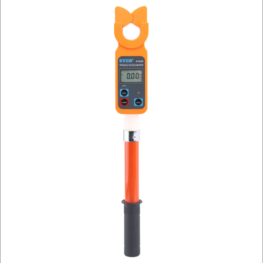
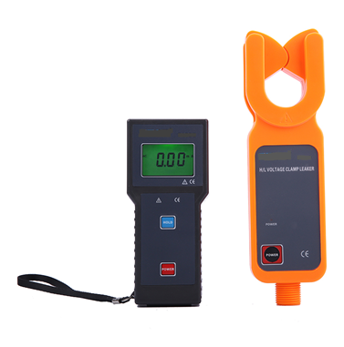
The GAOTek Portable H/L Voltage Clamp Current Leaker measures high voltage current with a 12.5 in (32 cm) insulating rod, adopting the latest CT technology and integrating mask digital technology. This instrument provides high precision, reliability, and stability with its integrated design between transducer clamp and domain. This leaker can be used to measure any wire with or without the insulation layer where the voltage is below 10 kV. The insulating rod is portable, moisture resistant, heat resistant, shock resistant, and insulating. It provides additional functionalities such as online current testing, peak and data holding, data storage, detection of high and low current in primary and secondary circuits separately, and provision of suitable calculations to conclude change in high and low pressure.
Key Features
- Highly accurate measurement of 0.01 mA-600 A current or leakage current
- Portable design which ensures safety
- Provides easy clamping and evacuation of the test wire with its special clamp leaker
- Data storage of up to 99 groups
- Automatic maintenance of test peak value
- Multiple additional functionalities
- Four digit LCD display with backlight
- Moisture, temperature and shock resistant insulating rod
- Automatic shut down if the device exceeds 15 minutes idle time
- Displays overflow in the measurement range
Technical Specifications
| Range | 0.00 mA ~ 600 A |
| Resolution | 0.01 mA |
| Frequency of current | 50 / 60 Hz Auto Identification |
| Test method | Clamp CT, Integral Method |
| Power | DC 6 V Alkaline Dry Battery (1.5 V AAA X 4) |
| Jaw size | Φ 1.2 in ( Φ 33 mm) |
| Test Accuracy (73.4 °F ±5 °F, below 80 % RH) | 0 mA ~ 299 mA : 1 % 5 dgt |
| 0.30 A ~ 49.9 A : 1.5 % 5 dgt | |
| 50.0 A ~ 199.9 A : 2 5dgt | |
| 200 A ~ 600 A : 3 5dgt | |
| 601 A ~ 1000 A : 4 % 5dgt | |
| Meter Dimension | 2.6 in × 9.6 in × 1.5 in(68 mm × 245 mm × 40 mm) |
| LCD dimension | 1.8 in × 1.1 in (47 mm × 28.5 mm) |
| Sampling Speed | About 2 times/s |
| Range Shift | Automatic |
| Circuit Voltage | Tests for the bare conductor below 1 KV, tests the current with insulation layer below 10 kV (operated with insulation rod) |
| Data Memory | 99 groups, ‘FULL’ blinks when the memory is full |
| Battery Voltage Indication | Below 4.8 V |
| Weight (including the battery) | Tester: 1.2 lbs(0.55 Kg) Including Battery and Rod
Total Quality of Meter: 3.2 lbs (1.2 Kg) Including Battery and Rod |
| Temperature and Humidity | Working: -4 °F ~ 104 °F (-20 ℃ ~ 40 ℃), below 80 % RH
Storage: -4 °F ~ 140 °F (-20 ℃~60 ℃),below 70 % RH |
| Insulation Intensity | AC 3700 V / rms (Between insulation rod and clamp core) |
| Structure | Anti-Dripping Type 2 |
Applications
- Transformer substations
- Power plant, industrial and mining enterprises
- Inspection stations
- Electrician maintenance departments for electrical current detection and field electrical operations
Warning
- Special attention need to be paid while using this meter particularly while measuring circuits with more than 100 V AC and above voltages
- If the voltage of tested circuit has exceeded 600 V, it must be used by connecting the insulation rod
- As the high voltage transmission line is very dangerous, the operator must get strict training and the relevant certification on high-pressure operation before using this meter and making a field test
- It is strictly forbidden to use this meter to test the wire with voltage over 1 KV which is without any insulation or convergence generatrix
- Please pay attention to marked words and symbols on panel or backboard of this meter
- Please do not put or store this meter in place of high temperature, with moisture, with frozen dew or with direct daylight radiation for a long time
- Please note the battery polarity when replacing the battery and remove the battery if you expect not to use this meter for a long time
- It must be operated by qualified staff that has the authorization of tearing down or repairing this meter
- Please do not use it when there is any damage on the transducer clamp or other parts of this meter
- To avoid the impact of transducer clamp, the meter has to be maintained regularly. Do not use corrosive or coarse materials to clean, but use soft cloth. Dip the cloth in a clean anti-rust desiccant lubricant (such as WD-40) wipe it gently
- In case of any danger, stop using it and seal it before sending to the authorized agency
- The danger symbol on the meter is indicated to the user. The user most operate safely in this case
- The extremely dangerous symbol is indicated to the user. The user must operate safely in this case
- It is suggested to conduct an insulation intensity test at least once annually. (AC 3700 V/rms. Between insulation pole and clamp core )
Ordering Information
| Model | Range of measurement | Accuracy | Jaw Specification |
| GT00YA00ZX | 0.0 mA -1000 A | 0.1 mA | Φ 1.8 in |
| GT00YA00ZX | 0.00 mA -600 A | 0.01 mA | Φ 1.2 in |
Structure

- Clamp
- Tester
- LCD Display
- PEAK Test Indication
- PEAK Key
- POWER Key
- HOLD Key
- Receiver
- Insulation Rod Connector
- Isolation Rod
LCD Display
- LCD Display Screen

- AC Symbol
- Low battery symbol
- Date storage symbol
- Date access symbol
- 2-digit Storage Data Serial Number
- Unit Symbol
- Date Locked Symbol
- Decimal System Radix Point
- 4-Digit LCD Digital Display
2. Explanation for Special Symbols
- Low battery symbol, when the voltage of battery is lower than 4.8 V, this symbol will be displayed. Please replace the battery in time
- “OL A” This symbol indicates that the current on test has exceeded the maximum measurement limit of the meter
- “MEM” Memory mode, it will display during the data storage process
- “Full” symbol, when the storage memory has been filled with 99 groups of data. It will display “FULL” symbol by flash, which means it cannot continue to store any more data
- “MR” data access symbol, which is displayed during data lookup. It will display the serial number of data in storage
- “End” exit symbol, it will be displayed during the exit
- “dEL” data delete symbol, it will be displayed when data is deleted
3. Display Demonstration
- The current on test is 0.002 A (2 mA)

2. Locked display Data –
a. The data is automatic stored as group 3
b. The current on test is: 5A

3. The current on test is: 571A
a. Low battery symbol. Please replace.

4. Look up data of group 3 in storage
a. The current on test is: 160.5A

5. “FULL” flash display
a. Storage is full of 99 groups
b. It can’t store more unless data is deleted from storage

6. “dEL” Indication of data delete

7. “End” Indication of exit

Operation
| |
Please check all parts of the meter carefully before usage to see if there is any damage. Make sure there is no damage before usage |
| Install the battery as per the instructions in the manual |
1. Power On/Off
- Press POWER button to power on. The instrument will display the LCD screen in normal testing mode. If LCD display is relatively dark after power on, it is possible that battery voltage is a bit lower. Please replace the battery. 15 minutes after power on, if it remains idle, an auto-power off procedure starts to preserve the battery life and LCD will continue to flash until the device switches off completely after 30 seconds. In case the LCD flashes continuously, press POWER button, then the meter will continue to work
- Under HOLD mode, press POWER button for power off
- Under general test mode, press POWER button to power off
- Under PEAK testing mode,press POWE button to power off. Under data reference mode, firstly press POWER button for more than 3 seconds to exit from data reference mode. Return to normal test mode, then press POWER button to power off. During the exit from data access, it will display “End” symbol.
2. General Test
| |
High voltage, extremely dangerous! It must be operated by qualified a staff that has acquired authority. The operator must strictly abide by the safety rules. |
| Dangerous! It cannot be used to measure the bare conductor over 1 KV voltage or convergence generatrix. Otherwise there are chances of personal damage or equipment damage to be caused |
a. During the test, LCD will display the real time tested current value and LCD data will vary with the current change. When the tester is removed from the lead on test, it does not preserve the test result. LCD display will return to zero.
b. Normal testing mode is suitable for close distance measurement and circuit test by direct read of LCD data
c. After normal boot, place the lead in the middle of clamp transducer domain, as shown in Figure A
d. With the meter transducer domain perpendicular to the lead, push the meter forward to clamp the lead on test, the result is displayed on the LCD
e. If “OL A” is displayed, it means that the lead current on test has exceeded the maximum volume on the level. Please select a higher gear level or a meter with greater measurement limit
f. To pull backwards, remove from the lead on test, as shown in Figure C. On removing, please try to keep the meter transducer domain perpendicular to the lead when moving away.


g. Under HOLD mode, press HOLD button to cancel HOLD function and return to normal testing mode
h. Under data reference mode, press POWER button for more than 3 seconds to exit from data reference mode and return to normal test mode
i. In PEAK testing mode, press POWER button to exit from PEAK testing mode and returning to normal test mode.
j. After data deletion, it will return to normal test mode automatically.
| |
Attention! When test has been completed, please remove the meter away from the lead on test for safety |
1. PEAK Test
PEAK test is the maximum current test. The meter will make automatic comparison on the changes in the measured current, indicating the maximum value and maintains it. When the meter is removed away from the lead on test, the test result will be kept consistent, suitable for the circuit test on the LCD data which is hard to be read directly.
Under the normal test mode, press PEAK button, PEAK indication light will be bright and enters into PEAK testing mode. That means the meter will display and keeps the maximum value in the test automatically.
Under any other mode, it must be returned to normal testing mode and then make PEAK testing according to the above operation.
Press POWER button to exit from PEAK testing mode and return to normal testing mode. It will display “End” symbol during the exit.
2. Data Maintenance
Under normal testing mode, press HOLD button until the LCD displays “HOLD” symbol. Press HOLD button again to release the data lock and return to normal testing mode. “HOLD” symbol disappears.
3. Data Memory
Under normal testing mode, press HOLD to switch to data storage. At the same time, meter will automatically form serial numbers and displays the current preserved data. During storage, “MEM” symbol will be flashed once. This meter can store 99 groups of data. In case the memory is full, “FULL” symbol will be displayed continuously, and it cannot continue to store data until the previous memory is cleared.
4. Data Reference
Under normal test mode, press PEAK + POWER button to enter data reference mode. “MR” symbol is displayed and meanwhile data saved in the group 01 is displayed automatically. Then press PEAK or POWER button to read the stored data by turning upwards or downwards in cycle. It will return to the group 1’s data automatically after reaching the last group’s data in storage.
Press HOLD button to exit from data reference mode and returning to normal test mode. During the exit, it will display “End” symbol.
5. Data Deletion
Under data reference mode, press PEAK + POWER button to delete all the data in storage and return to normal test mode. During the deletion of data, it will display “dEL” symbol.
Replacing Batteries
| |
Warning! In case the battery’s cover board is not closed properly, it is forbidden to conduct the test as it is dangerous. |
| Pay attention to the polarity of the battery, in case of damage to the meter | |
| Do not mix in the use of new and old batteries |
- When the battery voltage is below 4.8 V, the meter will display “
 ” symbol, indicating that the batteries have no sufficient power. Please replace the batteries.
 - Power off to make sure the meter is off. To loosen two screws of the battery cover board, open the cover board to replace brand-new qualified batteries on. It should Special attention should be paid to the battery specification and polarity. Cover the board well and fasten the two screws
- Press POWER button to check whether the meter can be powered on normally. If not, please repeat the operation according to step 2.


Accessories
| Tester | 1PC |
| Insulation Rod (12.5 in) | 1Section |
| Meter Box | 1PC |
| Battery (Alkaline Dry Battery AAA) | 4 PCS |
| User’s Manual/ Maintenance Card/ Conformity Certificate | 1 SET |


