Description
Overview
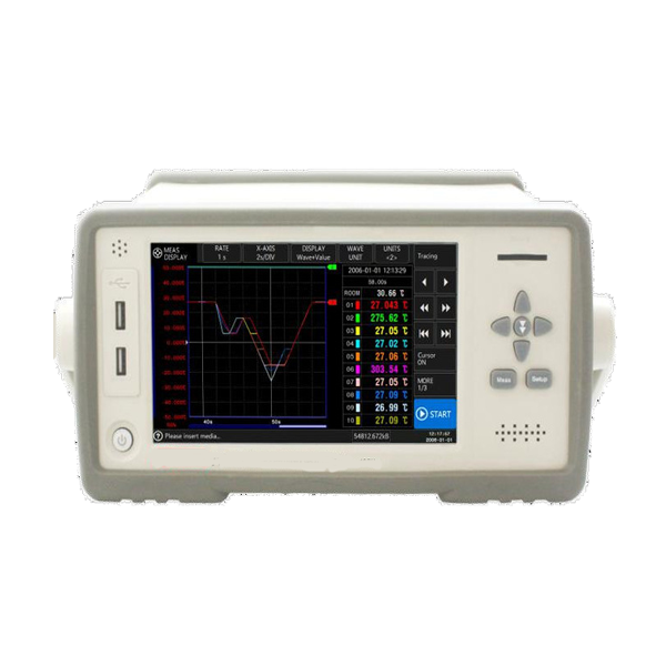
This instrument adopts Applent enhanced PC remote control commands, that are compatible with SCPI (Standard Command for Programmable Instrument), and realize high-efficient remote control and data acquisition functions. In order to apply to a live test, the instrument adopts a high voltage buffer circuit, MCU and IU can withstand voltage 300VAC, allow MAX withstand voltage 300VDC for each channel. There is a 80MB high capacity data cache inside the instrument, used to record in real-time, which can save 5.5 hours of data under a 10ms sampling rate.
The instrument supports four USB2.0 host interface and one SD card interface. The instrument configures comparator, and optional Handler (PLC) interface, output 10 channels NG signal. Built-in LAN interface, RS-232C interface and USB232 interface also have optional RS485 and Wireless LAN module. This temperature meter can be applied in many areas, which include fuel cells, electro bile batteries, lithium batteries, acid battery pack’s development and maintenance, LED and related circuit’s development, cars and their parts’ evaluation and measurement, daily maintenance of automatic equipment, factory monitoring, power devices and other electronic components’ measurements. From stationary data logging equipment to handheld, water-resistant data logger devices, the GAOTek’s multi-channel temperature meter lends itself to the multipurpose nature of the data logger and diverse measurement parameters.
Key Features
- 7 inches big LCD display screen, 3 types of display fonts.
- Adopts real-time FPGA circuit high sampling rate.
- Cold Junction Compensation, various types of input signals.
- Standard configuration USB-disk interface, support high capacity storage device.
- Standard configuration RS232C interface and USB interface, SD card interface, LAN interface
- Built-in high capacity data buffer, real-time record data.
Technical Specifications
| Graduation | Thermocouple: J/K/T/E/S/N/B/R |
| Accuracy | 0.2% |
| Range | -454F~3308F(-270°C~1820°C ) |
| Resolution | 0.01°C ( varies, depends on graduation) |
| Channels | 10 channels |
| Speed | 50ms/channel |
| Correction | Error correction for each channel |
| Comparator | High/low beep Individual setting high/low value for each channel |
| Interface | RS232C; USB-disk; SD card; USB communication; HANDLER interface |
| ATS47 data acquisition software | |
| Cold Junction | Accuracy: 32.18F(0.1℃) |
| 7 inches TFT-LCD with touch screen, true-color LCD display, broken thermocouple check function | |
| Voltage:85VAC~260VAC Frequency:50Hz/60Hz Power:30VA | |
| 11.41X5.11X14.17 inch (290mm(Width)x130mm(Height)x360mm) (Depth) 11.02lbs.(5kg ) |
|
| K type thermocouple 10 pcs (2m/pc); ATS47 data acquisition software |
How to Use
Connection of Voltage
Please connect voltage source’s positive pole to input terminal’s positive pole and connect negative pole to input terminal’s negative pole, otherwise, instrument will display negative value.
Connection of Thermocouple
Instrument supports 8 types of thermocouples; the connecting method for each type of thermocouple is the same. Please plug 2 terminals of the thermocouple to positive and negative test terminals; generally speaking, red wires to positive pole, black wire to negative pole.
Customizing Setup
Press [Setup] key or lightly touch the page title, then lightly touch the [SETUP] button in the functional field. The instrument will enter <SETUP> Page. All setup that is related to channel and <MEAS DISPLAY> Page and <DATALOG> Page is operated in <SETUP> page. On <SETUP> Page, the settings include the following parameters:
- Channel turn on/off
- Input type
- Channel color setup
- Range
- Curve graph lower limit value
- Curve graph upper limit value
Channel [ON/OFF]: Users can independently turn off each channel, after turning off, all parameters at current channel is set as unavailable.
Input [Type]: Each channel can individually set its input type, as the instrument supports various types of inputs and each input type varies; DC-V and thermocouples (TC-K, TC-J, TC-E, TC-T, TC-N, TC-S, TC-B, TC-W, TC-R) adopts a 2 terminal method to test, 3-wire RTD adopts a 3 terminal method to test, and 4-wire RTD and DC-R adopt a 4 terminal method to test. After setting the input type, please make sure the input terminal is correct.
Steps of Setting Upper/Lower Limit
- Enter <SETUP> Page
- Touch the screen & click or use the cursor to select [Upper/Lower Limit] field;
- Touch the screen function key field at right side, then click & select Upper/Lower Limit.
[Auto Save] Setting Value
When powered off, the instrument can save the revised data in the <SETUP> page into the disk automatically, and when users power on the apparatus the next time, the data will be available. “[Auto Save] function” must be set by the [Auto Save] option in the [File] page; set [Auto Save] option as [file 0] or [Current File]
Customising System Configurations
Lightly touch the page title, then lightly touch the [SYSTEM CONFIG] button in the functional field to enter the <SYSTEM CONFIG> page.
<SYSTEM CONFIG> page includes the following settings:
- Date/Time Setting
- Language Setting
- Data Logging
- Value Display Font Setting
- Measurement Related Setting, Local Network Connection
- WIRELESS LAN Connection, Communication Setting


