Description
Features
- Handheld, lightweight and easy to carry.
- Anti-seismic, shock and drop resistant sheath for field measurements and on-site measurements.
- 1310 nm/1550 nm/1625 nm wavelength with belt filter, supports FTTx online test.
- 8 m event blind zone, simple test of fiber patch cord.
- Starts measurement immediately in 3 seconds.
- Maximum measure distance of 99.41 mi (160 km).
- Can store more than 10000 curve information.
- Various test modes: automatic / manual / average / real time.
- Simple and user-friendly key design: In key operation, hotkey function, quick locating and event analysis points are integrated.
- Intelligent testing to ensures simple operation and great functions.
- Optical alarming function.
- Optional large-capacity SD card.
- Low power consumption design; optical lithium battery
- Multiple light outputs, FC as standard ST/SC optional and exchangeable VFL (visual fault locating) function.
- OTDR Viewer software for data analysis, editing and printing.
Applications
- Construction and maintenance of telecommunication projects
- Construction and maintenance of CATV projects
- Generic cabling system
- Production and research of optical devices
- Other fiber-optics projects
Technical Specifications
| Wavelength | 1310 nm / 1550 nm | 1310 nm / 1550 nm | 1625 nm | 1625 nm |
| Dynamic Range 1 | 28 dB/26 dB | 32 dB/30 dB | 30 dB | 33 dB |
| Pulse Duration (ns) | 10/20/50/100/200/500/1000/2500 | 10 /20/ 50 /100 /200 /500 /1000/2000/5000/10000/20000 | ||
| Max Measuring Distance | 0.62 mi – 74.56 mi (1 Km -120 Km) | 0.62 mi – 99.41 mi (1 Km-160 Km) | ||
| Sensing Fiber | Single mode fiber | |||
| Even Dead Zone2 | ≤ 1.8 m | |||
| Attenuation Dead Zone2 | ≤ 10 m | |||
| Attenuation Detect Accuracy | ±0.05 dB/dB | |||
| Loss Threshold | 0.01 | |||
| Loss Resolution | 0.01 dB | |||
| Sampling Resolution3 | 0.16 m – 5 m (0.16 0.32 0.64 1.28 2.56 5.08) | |||
| Distance Measure Accuracy4 | ±(1 m + 5 × 0.005% × distance + sampling space) | |||
| Data Storage | More than 10000 records | |||
| Storage Format | .sor bellcore file | |||
| Averaging Time | 5 s, 15 s, 30 s, 1 min, 2 min, 3 min | |||
| General Specifications | ||||
| Dimensions (H×W×T) | 210 mm × 112 mm × 67 mm (8.27 in x 4.40 in x 2.63 in) | |||
| Weight | 1 kg (2.2 lbs) | |||
| Screen Resolution | 320 x 240, 3.5 inch. | |||
| Temperature | Operating Temperature: 0 ℃ to 50 ℃/32 °F to 122 °F | |||
| Storage Temperature: -20 ℃ to 60 ℃/-4 °F to 140 °F | ||||
| Relative Humidity | 0 %-95 % (non-condensing) | |||
| Battery Life | Lithium battery; continuous operating time ≥ 10 h (with optical ordinary dry batteries) | |||
| Interface Type | ||||
| Connector | FC(ST/SC Interchangeable)/PC | |||
| Connectivity | USB/SD card | |||
| Matching Function Modules | ||||
| Visible Fault Locator | Wavelength: 650 nm;
Farthest distance test: 3.10 mi (5 Km) |
|||
| Note: The Specification describes the guaranteed performance with the typical PC type connector during the measurement. The uncertainty because the refractive index of the fiber is not considered.
1The dynamic range (SNR) of 1 is measured based on the maximum pulse width and a mean time of 3 minutes. 2Conditions for dead zone measurement: reflection strength below -45 dB, Event Dead Zone with 10 ns pulses width measurement, Attention Dead Zone with 50 ns pulse width measurement. 3The products with different specifications will have the different sampling rate. 4The uncertainty due to the refraction index of the fiber is not considered. |
||||
Ordering Information
| Module Number | Wavelength | Dynamic Range |
| GAO-OTDR-113-A | 1310 nm / 1550 nm | 28 dB / 26 dB |
| GAO-OTDR-113-B | 1310 nm / 1550 nm | 32 dB / 30 dB |
| GAO-OTDR-113-C | 1625 nm | 30 dB |
| GAO-OTDR-113-D | 1625 nm | 33 dB |
Packaging List
| Sr. No. | Item Description | Quantity |
| 1 | OTDR main unit | 1 |
| 2 | FC connector, ST connector and SC connector | 1 (each) |
| 3 | User Manual | 1 |
| 4 | USB data cable | 1 |
| 5 | OTDR Viewer Software CD | 1 |
| 6 | Power adapter | 1 |
| 7 | Cleaning cotton swab | 1 |
| 8 | Portable backpack | 1 |
| 9 | Certificate of quality | 1 |
Additional Information
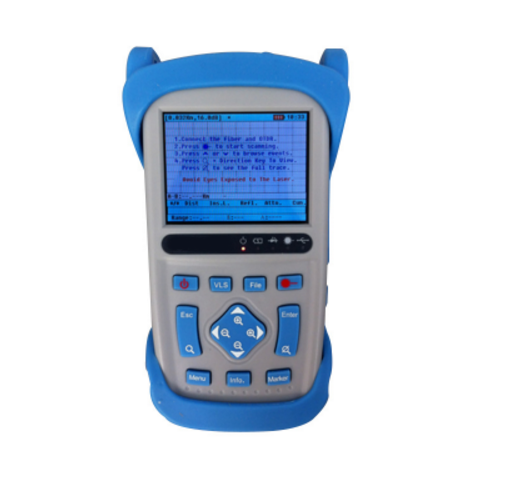
- VLS- Turning on or off the visible red light (CW/1Hz)
- Power- Starting or stopping the instrument
- Esc- Exiting from the current menu or cancelling the current operation Upward direction key
- Search- Second function key (compound key)
- Menu- Opening or exiting from a menu
- Leftward direction key
- Info- Displaying the trace parameter information
- Downward direction key
- Marker- Switching between posts A and B
- Rightward direction key
- Global trace display
- Enter- A confirmation key
- Upward direction key
- Enabling or disabling the measurement mode
- File- Opening or closing the file menu
- Display area of LCD
- Red light outlet- output frequency (CW/1Hz)
- OTDR interface- Used as an internal light source outlet for OTDR function measurements
- Memory card interface
- USB communication interface
- Power interface- To connect a standard power adapter
Directions for Use
Definitions of the parameters used by the instrument
| Scanning parameter | Definition |
| 1. Distance Range | The corresponding optical fiber length of the whole trace |
| 2. Pulse Width | Width of the laser pulse emitted by the OTDR to the optical fiber |
| 3. Mean Time | Duration of one measurement |
| 4. Laser Wavelength | Choosing the laser wavelength for measurements |
| 5. Index of Reflection | Index of reflection of the optical fiber (it has an impact on the transmission speed in the optical fiber) |
| 6. Scattering Coefficient | It has an impact on the backscattering power of light in the optical fiber |
| 7. Non-reflection Threshold | The events with an insertion loss larger than this threshold will be in the event list. |
| 8. Reflection Threshold | The reflection events with a reflection strength equal to or larger than this threshold will be in the event list. |
| 9. Ending Threshold | The first event with an insertion loss equal to or larger than this threshold will be regarded as end of the optical fiber and all the events following it will be ignored. |
| 10. Restore Defaults | Defaults set for the scanning parameters before delivery |
| System parameter | Definition |
| 1. Auto Shutdown | Choosing between Shut, 10 min., 30 min. and 1 h |
| 2. Brightness | Adjusting the LCD contrast |
| 3. Lang. | Choosing between a Chinese interface and an English interface |
| 4. Date | Date setup |
| 5. Time | Time setup |
| 6. Length Unit | Unit used in measurements by the instrument |
| 7. Restore Defaults | Defaults set for the system parameters before delivery |
Menu and submenus
The Menu includes File System, Parameter Setup, System Setup, Instrument Related Information, and Exit. See the figure below.
【Operate】Menu
- Press the “Menu” key to enter the menu.
- Press to choose the item to be set.
- Press Enter to confirm, or ESC or EXIT to exit.
File System
File System includes Open, Saved As, Delete and Format. Enter it through the “File” submenu under “Menu”.
Open
Open a file directory
First, enter the first-level directory.
- Press to choose the file folder.
- Press Enter to enter the second-level directory, or ESC or CANCEL to exit from the file system.
Open a file
- Press to choose the file to be opened.
- Press Enter to open the file, or ESC or CANCEL to exit from the file system.
Saved as
Press the direction keys to move to the figures or letters. Press Enter and input the file name. If the file name is wrongly input, press “<―” to erase the wrong part. After the file name is input,
- Press the direction keys to move to the figures or letters. Press Enter and input relevant information. Press “<―” to erase the wrongly input part.
- After the file name is edited, press ESC. After that, the cursor will move the “Save”. Press Enter.
Delete
Delete a file folder
- Press and . After that, the cursor will move to the file folder to be deleted and press MARKER for choosing.
- Press ESC. After that, the cursor will move to “Delete”. Press Enter.
Delete a file
- Press . After that, the cursor will move to the file to be deleted and press MARKER (A-B) for choosing. This step may be repeated to choose multiple files.
- Press ESC. After that, the cursor will move to “Delete”. Press Enter.
Measurement Instructions
Power on
Make sure the battery has been installed or the power adapter has been inserted and there is no light entering the optical port of the instrument. Press for 3 seconds to start. After that, a startup interface will appear.
Connect an optical fiber
Connect the optical fiber with the optical port of the CuteOTDR by aligning with the locating hole and tightening the thread.
Connector cleaning: Clean the optical fiber connectors and inspect whether they are FC or PC connectors; connect the optical fiber with the instrument.
Measure an optical fiber in the Auto mode
In the Auto mode, the instrument will automatically estimate the optical fiber length, set the sampling parameters, acquire curves and display the acquired curves.
The following parameters can be set directly in the Auto mode.
Testing Wavelength, Mean Time, Index of Reflection, Scattering Coefficient, Non-reflection Threshold, Reflection Threshold, and Ending Threshold
Of all the other parameters, the application will execute the ones defined in the Manual mode (except for those always to be analyzed after measurements).
In the Auto mode, the application will automatically set the sampling parameters to be optimal values according to condition of the optical fiber link currently connected with the instrument.
Measure
Choose Auto behind Distance Range and hold. In the startup interface, press to start a measurement. The waiting time may differ with the specific parameters and mode. The interface will then display contents such as the measurement progress and the measurement stage. After the measurement, a result display interface will appear automatically. Press at any time in the measurement can stop measuring and analyze the trace.
Measure an optical fiber in the Manual mode
In the Manual mode, user sets the designated measurement parameters manually. After that, the instrument will quickly and purposefully display the scanning results for use by professional users.
The parameters needing to be set include:
Distance Range: Set a Km value larger than the actual length.
Index of Reflection: Set the index of reflection of the optical fiber to be measured.
Pulse Width: A narrower pulse width can guarantee better detection of near or short-distance events; however, long-distance events cannot be acquired due to a too weak signal. A wider pulse width guarantee better detection of long-distance events; however, event detection may fail in near places due to signal saturation. Thus, the pulse width should be flexibly chosen in actual measurements.
Measuring Duration: The larger the measuring duration, the higher the signal-to-noise ratio; however, the waiting time will be longer. Thus, a longer measuring duration is recommended.
Non-reflection Threshold: The attenuation events or false gain events larger than this threshold will be detected.
Reflection Threshold: The reflection events larger than this threshold will be detected.
Scattering Coefficient: Set the scattering coefficient of the optical fiber to be measured. This parameter has an impact on calculation of the index of reflection.
Ending Threshold: The first event with an insertion loss equal to or larger than this threshold will be regarded as end of the optical fiber and all the events following it will be ignored.
Parameters can be set through menus of the instrument. If the optical fiber parameters are not clearly defined, the factory defaults of the instrument may be used directly; however, this will result in larger errors of the measurement results.
Measure
Set and hold all the parameters. In the startup interface, press to start a measurement. The waiting time may differ with the specific parameters and mode. The interface will then display contents such as the measurement progress and the measurement stage. After the measurement, a result display interface will appear automatically. Press at any time in the measurement can stop measuring and analyze the trace.
Save
After a measurement, user may enter the result saving interface directly by pressing hotkey File.
Upload data to PC
- Connect the CuteOTDR and the USB interface of a PC through a USB cable.
- Start the Cute
- Copy the curve content on the TF card.
Visual optical fault locating
The instrument can realize visual optical fault locating. The output wavelength and frequency are 650nm and CW/1Hz, respectively.
Operating steps: Connect an optical fiber with the red light output interface. CW red light and 1KHz red light will be output after VLS is pressed for the first and second time, respectively, and red light output will be disabled after the key is pressed for the third time.
Power off
Auto shutdown: If the power saving mode (namely the auto shutdown event) is chosen, the instrument will be powered off automatically after the set auto shutdown time is reached, no matter the instrument is powered by a battery or a power adapter and no matter whether there is key operation in the period.
Manual shutdown: If is long pressed in any condition, the instrument will shut down automatically.


