Description
Overview
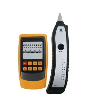
GAOTek Multi-Functional CCTV Tester with Signal Transmit (Lt Wt) is a professional networking cable inspection device that performs wiring tracing, cable order verifying and wiring faults inspection functions. Its cable tracing function helps users to isolate the cables from a bundle. Its cable order verifying function helps users to detect the characteristics such as open circuit, short circuit and mis-wiring of the cables.
Key Features
- Long distance wiring tracing.
- Cable order verifying function.
- Wiring voltage existence inspection.
- Wiring voltage positive or negative characteristic measuring function.
- Cable shorts inspection.
- Low battery indication.
- Tracing sensitiveness and volume adjusting.
- Headphone jack output.
- Flashlight.
Applications
- Wiring tracing
- Cable order verification
- Wiring faults inspection
Technical Specifications
| Transmitter | Receiver | |
| Weight | 0.26 lbs (119.2 g) | 0.15 lbs (68.8 g) |
| Dimension | 2.51 in × 1.22 in ×4.68 in (64 mm × 31 mm× 118.9 mm) | 1.91 in × 1.02 in × 4.60 in (48.6 mm× 26 mm× 117 mm) |
| Power | 1.5 V batteries (3) | 6F22 9 V battery |
| Signal tracing transmit distance | >0.62 mi (1 Km) | |
| Display | LED | |
| Low battery prompts | Yes | |
| Volume adjustment function | Yes | |
| Operating temperature | 14 ℉~ 104 ℉ (-10 ℃ ~ 40 ℃) | |
| Operating Humidity | 10 %-95 % RH | |
| Storage temperature | -4 ℉ ~ 140 ℉ (-20 ℃ ~ 60 ℃) | |
Packaging List
| No. | Item Description | Quantity |
| 1 | GAOTek Multi Functional CCTV Tester with Signal Transmit (Lt Wt) | 1 |
| 2 | 1.5V batteries | 3 |
| 3 | TEU | 60 |
| 4 | 6F22 9V battery | 1 |
| 5 | User Manual | 1 |
Product Description

Name of the Components Buttons
a) RJ45 interface 1) Power: Power button
b) RJ11 interface 2) V: Voltage test button
c) Function indication light 3) Ω: Cable shorts, opens inspection
d) Housing 4) TEST FAST: Fast cable order verifying button
e) Signal tracing sensor 5) TEST SLOW: Slow cable order verifying button
f) Flashlight 6) SCAN FAST: Fast tracing frequency button
g) Operation indication light 7) SCAN NOR: Normal tracing frequency button
h) Headphone jack 8) SCAN SLOW: Slow tracing frequency button
i) Volume control wheel
j) Scan cable tracing button
k) Flashlight switch
l) Cable order verifying lights section
m) RJ45 cable order verifying socket
n) Audio output
o) Battery door
Operation Instructions
Power on/off (POWER)
Press the power button for 2 seconds to turn on the device and the power indication light lights up; press the power button for 2 seconds to turn off the device.
Cable Tracing Function
The cable tracing function helps users to isolate the cables that they want from a bundle (such as Internet cable, telephone cable, and video cable). There are two tracing modes. First mode is the default mode when the device is turned on. Second, press any button of the SCAN buttons, and switch back to the tracing mode from any other modes, the SCAN light lights at the same time. Plug one end of the wire into the transmitter’s RJ11/RJ45 interface directly or through the alligator clip. Press the SCAN button on the receiver; detect surrounding area of the other end of the cable (such as cable terminal, phone distribution frame, terminal box, computer network distribution frame). Comparing the sound level, the targeting cable has the loudest sound. In a noisy environment, if the sound is not very obvious, press any button of the SCAN buttons to switch the signal frequency, in order to identify if the sound signal is effective or not.
Cable Order Verifying (TEST)
The Cable Order Verifying Function helps users to detect these characteristics such as open circuit, short circuit, and mis-wiring of the cable.
- UTP computer network cable of IEEE 10Base-T, EIA/TIA 568A, EIA/EIA568B, AT&T258A, Token Ring etc. standards.
- 2 core and 4 core etc. telephone cables
- Any other metal cables
Press any button of TEST buttons to enter into the cable order verifying mode. OHM light lights, and the SCAN light flashes. Put one end of the testing cable into the RJ45 interface of the transmitter, plug the other end into the RJ45 interface of the receiver. Judge the condition of the wiring, based on the 8 indication lights on transmitter and receiver. When the cable is normal, the light would light in sequence. The cable order verifying function could test the condition of the shielding circuit (G), indicated by the 9th light. The cable order verifying function could be measured in either fast or slow mode.
Cable Voltage Test (V)
Cable voltage test function is designed to inspect some basic attributes of the wiring, such as the existence and positive or negative characteristic of the voltage. This function only requires the transmitter. Press the V button; get into cable voltage test mode, VOLT light turns on. Plug the alligator clip into the RJ11 socket of the transmitter and clip the Red & Black clip to the measuring wiring or plug the RJ11 telephone line directly into the RJ11 interface. The OHM or SCAN light would light, if there is a phone line voltage. When the SCAN light lights, the red alligator clip connects the anode, on the other hand, it is cathode, when the OHM light lights. This product is designed for weak current, such as phone line, do NOT use for strong current, in case of electric shock and damage to the equipment.
Cable Shorts Inspection
It is designed to detect the telephone cable (not connected to the network) whether or not has shorts. Press the Ω button, and the OHM light lights. Plug the alligator clip into the RJ11 socket on the transmitter, clip the Red & Black clip to the measuring wiring, or directly plug into the transmitter, for the phone that has Crystal head. When the SCAN light lights, it indicates there is a short.
Wiring Instruction
- Alligator clip wiring: Plug into the RJ11 interface, and clip the other end by the Red & Black clip.
- RJ45 Crystal head wiring: Plug one end into the RJ45 interface on the transmitter, and plug the other end to the network port.
- RJ11 Crystal head wiring: Plug one end into the RJ11 interface on the transmitter, and plug the other end to the telephone port.
Safety Information
Warning:
To prevent electric shock and personal injuries, please do not:
- Trace the cable with strong current lest personal injuries and/or equipment damage occur.
- Use the unit in thunderstorm weather lest it results in personal injury and/or equipment damage.
Cautions:
To avoid the damage to the device and detection, please pay attention to the following:
- Do not use the cable order verifying function for the cable that has electricity.
- Take out the batteries if the product is expected not to be used for a long time, to avoid erosion of the battery leakage which may result in poor battery contact.
- Do not dismantle the device. Please contact the local dealer to repair the product by authorized technicians.


