Description
Overview
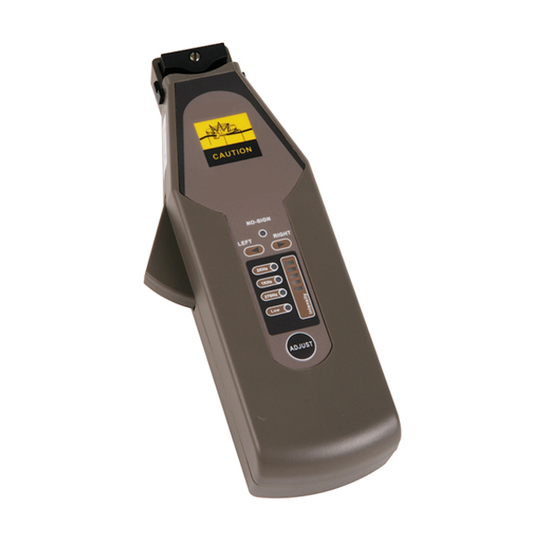
GAOTek Optical Fiber Identifier is a low cost, portable instrument which enables efficient, accurate and reliable data acquisition mainly designed to detect optical signals without disrupting traffic by implementing the non-destructive macro-bending technology which doesn’t disrupt traffic, damage or over-stress the fiber used. This device is mainly used during maintenance, installations, rerouting or restorations of fiber networks.
- Portable device
- ‘One button meter’ which is convenient and easy to use
- Detects a variety of optical tones 270 Hz, 1 kHz, and 2 kHz
- Powered by 2 units of 1.5V AA alkaline batteries
- RB 0.0098 in (0.25 mm), RB 0.35 in (0.9 mm), and RB0.11 in (3.0 mm) plungers available
- Low-cost and economical
Technical Specifications
| Recognizable Wavelength Range | 900 nm ~ 1650 nm | |
| Recognizable Signal Type | CW, 2 kHz, 1 kHz, 270 Hz ± 5 % | |
| Detector Type | In GaAs 2pcs | |
| Clamp Type | RB 0.009 in (0.25 mm) for bare fiber, RB 0.03 in (0.9 mm) for buffer, RB 0.011 in (0.3 mm) for jacketed fibers | |
| Sensitivity | @ 1310 nm | +11 dB to -20 dBm (Continuous Wave) +11 dB to -10 dBm (Modulated Signal) |
| @ 1550 nm | +11 dB to -30 dBm (Continuous Wave) +11 dB to -18 dBm (Modulated Signal) |
|
| LED Indicator | signal traffic; signal frequency (2 kHz/1 kHz/270 Hz); signal intensity (5 grades); low battery |
|
| Storage Temperature | -4°F ~ 158 °F (-20 °C to 70 °C) | |
| Working Temperature | 32 °F ~ 122 °F (0 °C to 50 °C) | |
| Power Supply | 1.5 V AA dry batteries* 2 pcs | |
| Dimensions (L x W x H) | 7.95 in x 2.44 in x 1.41 in
(202 mm x 62 mm x 36 mm) |
|
| Weight | 0.59 lbs. (270 g) | |
1 Preparing for Operation
1.2 Battery
This instrument is powered by two 1.5 V AA batteries. There is a “Low” battery indicator on the panel board. It turns on if there is not enough power to supply the instrument. That is when you should replace the battery with a new one. To replace the battery, please remove the battery plate on the back side of the instrument with a screwdriver.
Note: 1. It is advisable to use 1.5 V alkaline batteries. The Low Battery Indicator may light up if you use rechargeable batteries.
2 To eliminate the possibility of acid leakage, please take out the batteries if the unit is not used for a long time.
- Operation
2.1 Controls and connectors
| No | Key/Indicator | Note |
| 1 | Plunger | Three available types: H 0.009 in (0.25 mm) , H 0.03 in (0.9 mm), H 0.011 in (0.3 mm)) |
| 2 | Fiber Groove | A slot to place tested Fiber |
| 3 | PD Headstock | PD Headstock |
| 4 | No Signal Indicator | Lights up if there is no signal in tested fiber |
| 5 | Left Traffic indicator | Lights up if the signal in tested fiber is from right to left |
| 6 | Right Traffic Indicator | Lights up if the signal in tested fiber is from left to right |
| 7 | Signal Intensity Indicator | To show the signal intensity level; The higher, the stronger |
| 8 | 2 kHz Indicator | Lights up if the wave frequency is 2 kHz |
| 9 | 1 kHz Indicator | Lights up if the wave frequency is 1 kHz |
| 10 | 270 Hz Indicator | Lights up if the wave frequency is 270 Hz |
| 11 | Low Battery Indicator | Lights up when there is not enough power |
| 12 | Adjusting Key | Self-calibrates |
2.2 Powering on the instrument
Gently insert the tested fiber into the groove at the top of instrument. Pull the clamping trigger slowly to depress the fiber against the optical assembly. The instrument powers on when the detector plunger has closed and the fiber is in the appropriate position.
Note: Please be careful while placing the fiber in the provided slot. Force the fiber into the headstock. Misaligning the fiber may induce optical losses above what the specification demonstrates.
2.3 Traffic detecting
If the tested fiber is carrying signal, a Traffic Indicator illuminates to show the direction, left or right.
When no signal is present or the signal to be tested is too weak for the instrument to detect, the No Signal Indicator illuminates.
2.4 Frequency detecting
If the tested fiber is carrying 2 kHz, 1 kHz or 270 Hz modulated wave, the respective modulation indicator illuminates and the instrument makes a buzzing sound.
Note: The instrument may not recognize the frequency correctly if the signal is too weak or the frequency is not stable
2.5 Signal intensity
The signal intensity indicator on the panel board lights up to tell you how strong the signal is. There are 5 LEDS aligning in a line. More of them illuminate meaning the signal is stronger.
2.6 Self-calibrating
The instrument may need a little adjustment after long-term disuse or a sudden change of the environment such as temperature or light variation. Change the plunger to the H0.25 type, pull the clamping trigger, then press the “Adjust” key shortly to start the self-calibration which lasts about 1030 seconds. When it finishes, the instrument makes a buzzing sound and the “No Signal” Indicator blinks
Maintenance
- The testing performance will be affected when using different brands or types of fibers with various coating color.
- Please do not bend the fiber excessively; which may lead to miss-judgment on traffic or even breaking the fiber
- Keep the optical receiver clean and use cleaning oil when testing bare fiber to achieve the best performance.
- To clean the optical assembly, remove the clamp and gently clean the prism and optical windows using cleaning pads and cleaning oil. Do not immerse the plunger assembly in alcohol.
Safety Information
- Never look directly into optical outputs or a fiber while the equipment is on. Invisible laser beam may damage your eyes.
- Do not short-circuit the terminal of AC adapter/charger and the batteries. Excessive electrical current may cause personal injury due to fumes, electric shock or equipment damage.
- Connect AC power cord with the equipment and wall socket properly. While inserting the AC plug, make sure there is no dust or dirt on the terminals and both plugs are fully seated. Incomplete engagement may cause fuming, electric shock or equipment damage and may result in personal injury.
- Do not operate the equipment near hot objects, in hot environments, in dusty/humid atmosphere or when condensation is present on the equipment. This may result in electric shock, product malfunction or poor performance.
| Standard Accessories | 2*batteries, 3*adapter heads (RB 0.009 in (0.25 mm) , RB 0.03 in (0.9 mm), RB 0.011 in (0.3 mm)) carry bag, user manual, test report |
| Optional Accessories | Sun shield, RB 0.07 in (2.0 mm) adapter head |


