Description
Overview
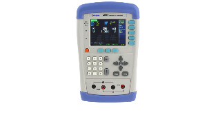
GAOTek Milliohm with Data Hold (Battery Identity test) test is used to judge the degradation of the battery by testing the internal resistance and voltage of the battery. Test range from 0.1 mΩ to 200 Ω, 0 – 50 V DC voltages, max reading of the resistance of 3200 digits and voltage of 5000 digits. It has an optional USB interface which can be used for remote control and data acquisition and analysis makes it more suitable for assembly line tests of all kinds of batteries. Accurate open voltage can be tested out by vectorless test theory. Professional sorting function and sorting sets of the beep make it more suitable for automatic assembly line tests.
Features
- Portable design with dual-color protective cast shell
- Battery and external power supply
- TFT-LCD display, 3.5 inches display, true color 16 M
- Automatic power off
- Double display: ΔABS, Δ% and sorting result
- Comparator function: GD/NG VFD show or Handler out
- Auto zero adjustments for each range
- Four terminal resistance measurements
- Mini-USB interface
- Compatible with SCPI command sets
- Keypad lock function
- Data hold function
- Adjustable background brightness
- Rechargeable Batteries
- Max power ≤5 W
- 8.4 V, Li-Battery 2200 mAh rechargeable battery
- Temperature compensation
- Customizable beep feature
Technical Specifications
| Parameters | AC resistance, DC Voltage |
| Accuracy | Resistance 0.5 % ± 5 digits
Voltage: 0.5 % ± 5 digits |
| Measurement Range | Resistance: 0.1 mΏ to 200.0 ΏV
Voltage: 0.0001 V to 50 V |
| Signal Source | AC: 1kHz
Open-Circuit Voltage: <30 mV Current: <15 mA |
| Range | Automatic, manual, nominal, 4 ranges |
| Speed | 2 times per second |
| Result Display | ABS/PER/SEQ |
| Display Max | Resistance : 3200
Voltage : 5000 |
| Max Resolution | Resistance : 0.01 mΏ
Voltage : 1 mV |
| Adjustment | Short-circuit reset to each range |
| Comparator | Voltage comparison separately, resistance comparison separately, voltage and resistance combination comparison and GD/NG sorting result display. Adjustable beep |
| Trigger | Internal, manual and remote |
| Test Terminal | 4 terminal shielding and external shielding ground section |
| Interface | Built-in-mini-USB charging interface
U disc interface |
| Power | Input: 100 V -240 V to 50 Hz/60 Hz 0.35 A
Output: 9V 1A DC 8.4v, Li, 2200 mAh rechargeable battery |
| Dimensions | 5.12 in x 8.29 in x 1.49 in
(130.23 mm x 210.76 mm x 37.88 mm) |
| Weight | 1.10 lbs (500 g) |
| Working Time | ≥8h @25 % Brightness |
| Temperature and humidity range: | 59 ◦ F to 95 ◦F (15 ◦C to 35 ◦C), 80 % RH or less |
| Storage temperature and humidity range: | 50◦ F to 104◦F (10 ◦C to 40 ◦C), 10 % to 90 % RH |
Additional Information
Application:
- Internal resistance and voltage of the battery
- Alkaline batteries, Life assessment lead batteries
- UPS online measurement
- Batteries identification test
- Super capacitor ESR measurement
- Contact resistance and internal resistance of battery
Main Functions:
Correction:
Short-circuit clear zero correction for all ranges.
Comparator (Sorting Function):
Set up the sorting function for GN/DG sorting
Comparator methods:
- Absolute value of tolerance ± TOL sorting
- Percentage tolerance %TOL sorting
- Sequence comparison sorting
Beep Feature:
- Beep: OFF/GD/NG
- System Setup
- Keypad lock function
- Time and Date settings
- Language switch option
- Administrator account settings
- Background brightness settings
- Auto power off settings
- Remote Control
- Max baud rate: 115200 bps
- SCPI available
- ASCII transmit
Interfaces:

- USB Host port
- Mini-USB Slave Port
- Reserved Interfaces
- Power Adaptor
- Power Adaptor
Replace Battery
The instrument has built-in rechargeable battery and it has been installed in the battery compartment of the instrument. Replace the battery according to the following procedure.

Power Supply:
The instrument can be powered by Li battery. When the battery is low, power adaptor is used to charge the battery.

Turn ON/OFF:
To turn ON/OFF the instrument press the power key.
Test Slots
Insert the cable box into test slots.

Clips and cables:
Using the clips and cables of other brands may cause damage and after 1 to 2 years the surface of the accessories may get damaged which will leads to inaccuracy.
Front Panel Summary:

<MEAS DISPLAY> Page
Press [Meas] key to enter <MEAS DISPLAY>Page.
The <MEAS DISPLAY> page includes following setup:
Trigger Mode [TRIGGER]
Measurement Range [RANGE]
Test Speed [SPEED]
Comparator [COMP] ON/OFF
[BEEP] Feature
Soft-key VIEW DATA – To Enter [VIEWDATA] page
Soft-key SAVE DATA – To Store current measurement result into internal flash disk
<MEAS DISPLAY>Page

[TRIGGER]
It supports Three trigger modes:
- Internal Trigger
- Manual Trigger
- BUS Trigger
Trigger Setting:
| Trigger | |
| Internal | Internal trigger |
| Manual | Press the [Enter] key once, the instrument runs a test cycle |
| BUS | The instrument runs a test cycle by receiving RS232 trigger command. |
- Procedure to set the trigger:
| Step 1 | Press [Meas] key to enter <MEAS DISPLAY> page | |
| Step 2 | Use cursor keys to select [TRIGGER] field | |
| Step 3 | INT | Automatic Internal trigger |
| MAN | Manual trigger by pressing [Trig] key | |
| BUS | BUS trigger by RS232 SCPI command | |
Resistance [RANGE]
It has three range modes:
- AUTO range
- Manual range
- Nominal range
Resistance Ranges:
| Range | Description | Pros | Cons |
| AUTO | Automatically.
Impedance range is automatically set by selecting the best range |
Convenient | Test speed is slower than manual ranging |
| HOLD | The instrument will always use the user-specified range | Highest speed | Set the range initially |
| NOMINAL | Automatically
Select the best range according to nominal value |
Best mode for sorting | Only available in sorting mode |
Resistance Measurement Range:
| Range | Range Name | Measurement Range |
| 5 | 2 kΩ | 200 Ω ~ 2.2 kΩ |
| 4 | 200 Ω | 20 Ω ~ 220 Ω |
| 3 | 20 Ω | 20 Ω ~ 220 Ω |
| 2 | 2 Ω | 2 Ω ~ 22 Ω |
| 1 | 200 mΩ | 200 mΩ ~ 2.2 Ω |
| 0 | 20 mΩ | 0 mΩ ~ 22 mΩ |
Procedure of setting the range:
Procedure to set the trigger:
| Step 1 | Press [Meas] key to enter measurement page | |
| Step 2 | Use the cursor key to select [RANGE] | |
| Step 3 | AUTO | Auto range |
| HOLD | Current range is hold | |
| NOMINAL | Select the range according to resistance nominal value [ResNom] | |
| INCR+ | Increase range | |
| DECL- | Decline range | |
The DC voltage measurement range cannot be selected. Instrument always use automatic mode.
Test Speed:
SLOW, MED and FAST test speed can be selected.
Procedure to set test speed:
| Step 1 | Press [Meas] key to enter measurement range | |
| Step 2 | Use the cursor key to select [SPEED] field | |
| Step 3 | SLOW | |
| MED | ||
| FAST | ||
Comparator [COMP]
Set the comparator parameter in <SETUP> page and the page is about how to turn on/off the comparator.
| Step 1 | Press [Setup] key to enter measurement range | |
| Step 2 | Use the cursor key to select [COMP] field | |
| Step 3 | OFF | Comparator off |
| ON | Comparator on | |
[BEEP] Feature:
Procedure to set the beep
| Step 1 | Press [Meas] key to enter measurement range | |
| Step 2 | Use the cursor key to select [SPEED] field | |
| Step 3 | OFF | Turn beep off |
| GD | Beep while pass | |
| NG | Beep while fail | |
Icons on <MEAS Display>
| Icon | Description |
 |
Powered by Li battery |
 |
Powered by external power supply |
| |
USB-Disk is available |
| H | Hold current data |
< SETUP> page
Press [Setup] key to enter <SETUP>page.
In <SETUP> page, if the testing is not progress the Instrument does not display the measurement result and comparator result.
The <SETUP> page includes following setup:
- Trigger Mode [TRIGGER]
- Measurement Range [RANGE]
- Test Speed [SPEED]
- Comparator [COMP] ON/OFF
- BEEP Feature
- Soft key CLEAR ZERO – Clear Zero Correction
- RESMODE – AC Resistance Sorting Methods
- VOLTCOMP– DC Voltage Sorting Methods
- ResNom – Input Resistance Nominal Value
- ResLow – Input Resistance Low Limit
- ResHigh – Input Resistance High Limit
- VoltNom – Input Voltage Nominal Value
- VoltLow – Input Voltage Low Limit
- VoltHigh – Input Voltage High Limit
Some settings can be also set up in <MEAS DISPLAY> page.

Short-circuit Clear Zero [CLEAR ZERO]
Press [Setup] key to enter < SETUP> page, and then press [CLEAR ZERO] soft key to do short-circle clear zero. Once it’s done with short-circuit clear zero the value will be saved into internal flash disk.
Note:
It is necessary to do short-circle clear zero. When replace the test fixture or test cables, it is must to do short –circle clear zero.
Connect the test clip as shown in the below figure.

RS232 [BAUD] rate
Connect the instrument to computer via Mini-USB to RS-232 port and the instrument will communicate with PC, meanwhile the keypad will be locked. Use the SCPI language in Mini-USB programming.
Mini-USB to RS-232 format:
- Data bits: 8
- Stop bits: 1
- Parity: none
| Step 1 | Press [SYSTEM] bottom soft key to enter <SYSTEM CONFIG> page | |
| Step 2 | Use the cursor key to select [BAUD] field | |
| Step 3 | 1200 | For the communication, converter opt with coupler isolation |
| 9600 | ||
| 38400 | ||
| 57600 | ||
| 115200 | Best for communication with PC | |
<SYSTEM INFORMATION>

| Step 1 | Press [Meas] or <Setup>key to enter main page |
| Step 2 | Press bottom soft key [SYSTEM] to enter <SYSTEM CONFIG> |
| Step 3 | Press soft key [SYSTEM INFORMATION] to enter <SYSTEM INFORMATION> page |
AC Resistance Range:
| Range | Max. Reading | Resolution | FAST | MED | SLOW | Test Current | |
| 1 | 200 mΩ | 220.0 mΩ | 0.1 mΩ | 0.8 % ± 4 | 0.6 % ± 3 | 0.5 % ± 2 | 1 mA |
| 2 | 2 Ω | 2.200 Ω | 1 mΩ | 0.8 % ± 4 | 0.6 % ± 3 | 0.5 % ± 2 | 0.1 mA |
| 3 | 20 Ω | 22.00 Ω | 10 mΩ | 0.8 % ± 4 | 0.6 % ± 3 | 0.5 % ± 2 | 10 µA |
| 4 | 200 Ω | 220.0 Ω | 100 mΩ | 0.8 % ± 4 | 0.6% ± 3 | 0.5 % ± 2 | 5 µA |
|
Open-circuit Voltage: < 30 m Vrms |
|||||||
DC Voltage Range:
| Range | Max. Reading | Resolution | FAST | MED | SLOW | |
| 1 | 5 V | 5.0000 V | 1 mV | 0.5 % ± 5 | 0.5% ± 3 | 0.5 % ± 2 |
| 2 | 50 V | 50.000 V | 10 mV | 0.5 % ± 5 | 0.5% ± 3 | 0.5 % ± 2 |


