Description
Overview
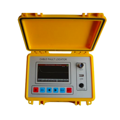
GAOTek Cable Fault Locator is a completely automatic device which adopts ARM, FPGA and Dot Matrix Color LCD display technology. This tester combines the principles of time domain reflectometer’s (TDR) pulse reflection testing and intelligent bridge testing (Bridge) both for the measurement of the exact fault location. The device is efficient to measure various faults of the cables such as the broken line, cross faults, earthing, poor insulation and poor contact of the lead covered cables as well as plastic cables. The device can test almost all the telecom cables also.
It is an effective tool to reduce troubleshooting time, improve work efficiency and reduce labor intensity of line maintenance staff. It also can be used in line projects acceptance and inspection of electrical cables.
Key Features
- Large color LCD Display (480 x 280 dot); humanized operation interface; six function keys and simple operation.
- Both pulse reflection testing (TDR) and intelligent bridge testing (Bridge) can test broken lines, crossing lines, poor insulation and other types of faults.
- Manual testing function is preserved.
- Full English Menu is easy to master and use.
- With megameter and ohmmeter, it enables to test insulation resistance and loop resistance.
- With USB Port, it is easy to upload testing data to computer.
- Rechargeable lithium battery, intelligent charging without duty.
- Small dimension, light weight and portable design.
Applications
- Measures the broken lines, crossing lines and low-resistance fault.
- Measures the line insulation electric resistance and loop electric resistance.
Technical Specifications
| Pulse Reflection Testing (TDR) | |
| Max range: | 4.97 mi (8 km) |
| Dead Zone | 0 ft (0 m) |
| Testing Accuracy | 3.28 ft (1 m) |
| Pulse width | 40 ns-10 μs with automatic adjustment |
| Adjustment | Automatic impedance balance adjustment |
| Automatic and manual gain adjustment | |
| Intelligent Bridge Testing (Bridge) | |
| Max poor insulation resistance: | 100 MΩ |
| Testing accuracy: | ±1%×cable length |
| The max length of testing cable | 9999 m |
| Charging time | 4 hours |
| Continued operating time | 8 hours |
| Dimension | 8.67 in × 6.29 in × 3.54 in (220 mm × 160 mm × 90 mm) |
| Weight | 2.20 lbs (1 Kg) |
Packaging List
| No. | Item Description | Quantity |
| 1 | GAO Tek Cable Fault Locator | 1 |
| 2 | Carry case | 1 |
| 3 | Re-chargeable battery and charger/adapter
|
1 |
| 4 | Test Line | 1 |
| 5 | User Manual | 1 |
| 6 | CD (Just for USB function) | 1 |
| 7 | U-disk (Just for USB function) | 1 |
Operating Instructions
When the lines have faults, you should firstly use testing board, megameter or multimeter to find the character and serious degree of cable faults, so as to choose the most suitable testing mode.
Testing Steps
1. Diagnosis of fault characters
The characters of telecom cable faults can be simply divided into the following several kinds:
Broken line:
One or many cable core line are broken and the communication is interrupted. This kind of fault should be tested with the pulse testing.
Crossed line:
It can be divided into the earthing, self-crossed and other-crossed lines, which mean the core line to the lead cover, between the identical couple of core lines, the insulating layer between the different couple of lines and the core is destructed; the insulating resistance drops to the very low degree (below several hundred to several thousand ohms), even can cause short-circuits; the communication quality comes under serious influences. This kind of fault can firstly is used the pulse testing method. When the waveforms are difficult to distinguish, and then change it to the electric bridge testing.
Bad insulation:
When the cable core insulation material is invaded by water or humidity, the insulating resistance will drop and cause low communication quality or even blocks. This kind of broken line is similar to self-crossed, other-crossed lines and the earthing. The fault resistance is a big (above several thousand ohms) and the fault degree is light. Usually, if the insulating resistance is smaller than 2M ohms, the communication quality will be affected; it needs to carry on the elimination. This kind of fault generally cannot be tested by pulse testing, but needs to change to the bridge testing.
Choose Testing Mode:
When the fault resistance is smaller than several hundred to several kilo ohms, we call it low resistance, otherwise, it is called the bad insulation or the high-resistance fault. High-resistance and low resistance have no explicit boundary.
The pulse testing is suitable for testing broken lines and low resistance crossed lines. Sometimes, the serious insulation can also use pulse testing. The pulse testing operation is direct-viewing, simple, no need the coordination of the other end, it is should be firstly used when testing.
The bridge testing can test the high-resistance bad insulation faults, but it needs to find a good line, moreover, it needs the coordination of the other end. The test preparatory work is also quite tedious. You should use the bridge method after confirming that the pulse testing can not test the fault.
Fault Range Finder:
During testing, it should firstly cut off the lines or equipment on both sides of the cable to be tested. Perform testing firstly in the equipment to fix the smallest segment of fault, and then carry on the repeated testing, on-the-spot to locate the precise fault point.
Fix Cable Fault:
You can locate the precise location of a fault on the basis of the testing results and the comparison of map data. When the map material is not entire or contains errors, you can estimate the approximate position of the fault according to the grasped cable situation. Then you can combine with the around environment to analyze the fault reasons until finding the cable fault. For example, there is a joint in the estimated range; it can approximately judge that the fault is in the joint. The further the range is, the bigger the testing errors are.
Pulse Testing – Pulse testing is for testing broken lines and low-resistance fault.
1.Testing principles
Pulse testing is a kind of remote testing method; one can locate the fault point without testing on the field or testing with end-to-end coordination. The principle of the theory is:
The instrument emits a pulse to the line, when the line has faults, the pulse reflection will change. If the come and back time can be measured, the location of the fault point can be detected.
Suppose the pulse transmission velocity in electric cable velocity is V, the come and back time that the pulse travels between the test point and the fault point is T, the fault distance is L, then:
- 2L = V T
- L = V T/2
For example, the sending end transmits a pulse to the cable, after 20μs, the sending end get the reflection pulse. If the pulse transmission velocity in the electric cable is 201 m/μs, the fault distance L is
L = 201×20/2 = 2010 m
2. Steps of locating fault point
Diagnosis of fault characters
To insure the accuracy of the testing of fault point, the testing personnel shall diagnose the fault characters correctly and then choose the most suitable testing mode. The characters of telecom cable faults can be simply divided into the following several kinds:
- Broken line
One or many cable core line are broken.
- Crossed line
The insulating resistance between the different couple of lines drops and causes the communication amplitude drops.
- Earthing fault
The insulating resistance between the core line to the lead cover drops and causes low communication quality
- Crosstalk noise
When the cable core insulation material is invaded by water or humidity, the insulating resistance will drop and cause low communication quality or even blocks.
- Bad insulation
The insulating resistance between different couples of lines and the core drops to a very low level, the communication quality comes under serious influences.
Fault Testing
Cut off the cable to be tested both side lines or equipment. Make sure the cable to be tested is free of voltage. Using this instrument to do intelligence testing first, if the fault cannot be detected and then you can change to manual testing.
Locating fault point
The tester will Judge the approximate location based on the test result, then check the cable, cable gland, cross boxes, etc., depending on the actual situation.
3. Intelligent Testing
Press “on”, connect the testing lead line and fault cable line. Press “Auto” and then the instrument will show the testing result.
Note: The default setting wave velocity is 200 m/μs, when you perform intelligence testing, the user shall check whether need to adjust the velocity (see “Adjust wave velocity” in the next section).
4. Manual Testing
The relevant setting and parameters will demonstrate on the underneath of the display screen. Press “Adjust” to adjust the setting and parameters.
(a) Gain– Press “Adjust” , until “Gain xx” shows reverse color display. Then press “◄” or “►” to adjust the amplitude (1~99 adjustable), press “Pulse“, the screen will display the wave after gain adjustment.
(b) Range– During manual testing, Range decides the maximum testing distance of the instrument, so the range value shall be chosen as longer than actual length of the cable to be tested. To adjust the Range, repeatedly press “Range”, until “Range xx” shows reverse color display. Press “◄” or “►” to adjust the Range.
(c) VOP– The precision of the wave velocity directly affects the precision of the testing result. So, the wave velocity shall be calibrated according to the cable characters. Press “Adjust” , until “VOP xx” shows reverse color display. Then, press “◄” or “►” to adjust the wave velocity.
Adjust the Range and Wave Velocity according to the characters and estimated length of the cable to be tested. Appropriately adjust the wave amplitude to make the waveforms on the display screen to be observed easily. Move the cursor to the inflection of the reflected waveform. The fault distance will demonstrate on the underneath of the display screen.
Intelligent Bridge Testing – The fault resistance of bad insulation is very high (above several thousand ohms) and is much bigger than the characteristic impedance of the cable; the pulse reflection is weak and is not easy to judge the fault point. At this time it needs to carry on bridge testing. The bridge testing in this instrument also has the simple megameter and the ohm meter functions.
1. Testing principles
As we know, there are certain resistances in the cable core line and resistance value in the unit length is same. Suppose the resistance of entire core is R, if you can test the core resistance from the fault to one end (test point) is Ra, and the core accurate length L is known, suppose the fault distance is La. Then:
La= (Ra/R) L
The core line resistance will be affected by changing temperature and different line diameter, but these influences are same in the cable span. Use the Ra/R ratio calculation method can eliminate these influences.
During testing, firstly, the instrument calculates Ra/R automatically, and then input some data manually to calculate La. This instrument adopts the intelligent electric bridge technology, so the user only needs to connect lines, input data and the length of partial line diameter; press “Auto”, and the fault distance will be calculated.
2. Bridge testing step
- Wiring:
The bad insulation faults divide into bad insulation of the core to the earth (earthing), the bad insulation between identical line couple and two core lines (self-crossed) and the bad insulation of different line couples (other-crossed) and so on so you must have an explicit judgment before wiring. We firstly take the bad insulation between core line and earth, for example to introduce:
- Before the test, it is better to fix the fault point in the small sector, like between two cross boxes. We carry on testing on one end in this sector, and wiring coordination with the other end. Here, we call the end, which carry on the testing end and the other are coordination end.
- Find out a core line, which has smaller insulation resistance to earth (note: it is a single line) for the testing, fault line cut off its both sidelines or equipment.
- Find out a core line, which has good insulation to earth (also a single line) for testing assisted line. Cut off the lines or equipment on both sides. The insulation resistance of the good line to earth is at least 100 times than the fault line on earth. The bigger, the better.
- Connect good line and fault line in the coordinate end. (i.e. Coordinate end loop).
- Connect the black clip, which is at the end of the testing line of the earth. Connect the yellow clip to the core line and the red clip connects to the fault core line. As shown in Figure below
Figure 1 : Wiring of Earthing Fault
- Except the line connection of black clip is different, the connection of other clips of wiring method of the bad insulation between identical line couple (self-crossed) and the bad insulation between different line couples (other-crossed) are as same as previous ones. Wiring method is as shown in Figure 1 and Figure 2
Figure 2: Wiring of self-crossed fault
- In the wiring process of bridge test, there should not have any mistakes of the judgment of faults, the selection of good line and fault lines, the good short connection of the core line in the coordination end, the wiring of the three clips. Otherwise, the testing is easily failed.
2. Test
If the wiring has no mistake, press “manual”, the instrument starts to test.
The instrument test line insulation resistance and loop resistance firstly. As shown at the top of the screen.
If there is no short connection on the coordinate end, then it demonstrats the insulation resistance value and “no loop” of the red and yellow clips to the black clip. By now it needs to inspect whether the wiring is correct or not, then test again.
Compare the values of two insulation resistances to distinguish the good and fault lines. The resistance of good line is big, and even to infinity (∝ indicates infinity, similarly hereinafter), the insulation resistance of fault line is quite smaller.
If the wiring is correct, the testing will carry on continuously, and finally obtain the ratio value of fault distance and cable length. Next, input cable span to get the fault distance. The entire test procedure probably needs one minute.
3. Data Input and Calculation
The last step is only tested out the ratio value of fault distance and cable span. It needs to input manually to get the data, such as cable length, and then calculate the fault distance (please note: the cable length here refers to the cable length in the testing fault sector, say the cable length from testing end to coordinate end). The cable length can be obtained through checking installation materials or the pulse testing of this instrument.
For example, the known length of the testing, fault section 0.61 mi (986 m), after testing, according to the following step input:
Press “Adjust”, the first place in “line span = 0000 m” is twinkling to prompt you to input data in this place. Because the cable length is 986 meters, the first place need not to modify.
Press “Adjust”, the second place in “line span = 0000 m” starts to twinkle.
Press “►” for nine times or press “◄” for one time, the demonstration becomes: fault distance/line span =0900 m”
Press “Adjust” again, the third place in “fault distance/line span = 0.55 mi (0900 m)” starts to twinkle.
Press “►” for eight times or press “◄” for two times, the demonstration becomes: “fault distance/line span = 0.60 mi (0980 m)”
Press “Adjust” again, the fourth place in “fault distance/line span = 0.60 mi (0980 m)” starts to twinkle.
Press “►” for six times or press “◄” for four times, the demonstration becomes: “fault distance/line span =0.61 mi (0986 m)”.
The instrument will automatically calculate the fault distance during the data inputting.


