


Description
Overview
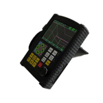
GADTek Flow Detector with Auto Calibration (Spheroidization Rate) is a high speed flow detector to locate, evaluate, and diagnose various defects with 28 DGS curves. This instrument has the embedded software within it which is very useful to update the status online. Spheroiduotion rate measurement is one of its best features and continuously works with the time of upto 12 hours. It complies with 14 standards of DAC. It is used as active safety inspection and service lite evaluation in aerospace, railway transportation and boiler pressure vessels.
Features
- Automated calibration of transducer Zero Offset and/or Velocity
- Automated gain, Peak Hold and Peak Memory
- Automated display precise flaw location (Depth d. level p, distances, amplitude, size dit Automated switch three staff gauge ((Depth d. level p, distances)
- 500 independent set-up, Any criterion can be input freely, We can work in the scene
- Without test block
- Big memory of 1000 A graph
- Gate and DAC alarm, Acoustic-Optical olarm
- USB port, communication with pc is easy
- The embedded software can be online updated
- LI battery, continue working time up to 12 hours
- Display freeze
- Automated echo degree
- Angles and K-value
- Lock and unlock function of system parameters
- AWS DI
- Dormancy and screen savers
- Electronic clock calendar
- There are 14 standards of DAC
- Automated make video of test process and play Connect the USB Disk, the length of video is unlimited
- Two gates setting and alarm indication
- High-speed capture and very low noise
- DAC, AVO, TCG, B Scan, Solid plastic housing (IP55)
- Automated calculation of the size of the flaw with wide bottom type in AVO function
- 5 dB DAC functions
- Provides high contrast viewing of the waveform from bright, direct sunlight to complete darkness and easy to read from all angles
- Powerful PC software and reports can be export to excel
Technical Specifications
| Scanning Range | 0 in to 393 in (0 mm to 10000 mm) |
| D-Delay | -20 ms to +3400ms |
| P-Dekay | 0.0 ms to 99.99 ms |
| MTIVEL | 1000 ms to 15000 ms |
| Working Mode | Single probe (receiving and sending), double probe (one for receiving and another for sending). Transmission (transmission probe) |
| Frequency Range | 0.5 MHz to 20MHZ |
| Gai Adjustment | 008 to 130 dB |
| Reject | 0% to 80% of screen height, step: 1% |
| Vertical Linear Error | Vertical linear error is not more than 3% |
| Horizontal Linear Error | Not more than 0.2% in the scanning range |
| Sensitivity Leavings | >262 dB |
| Dynamic Range | >234 dB |
| Alarm | Three modes, Le forbidden wave, loss wave and auto |
| A-Scan Display Area | Full screen or local A-Scan display freezing and de-freezing A-Scan filling |
| Data Save | 1000 A-Scan Images (including setting of instrument) |
| Standard Communication interface with PC | USB |
| Measuring Unit | Inches/mm |
| Battery | Li battery 7.4V 4800 mAh |
| Power Adaptor | Input 100V to 240 V/50 Hz to 60 Hz Output 9 VDC/15A |
| Working Temperature | -4°F to 122 °F (-20 °C to 50 °C) |
| Working Humidity | 20% to 90% |
| Dimension | 196 in x 629 in x 9.37 in (50 mm 160 mm 238 mm) |
| Weight | 2.20 lbs (10 kg) |