
Description
Overview
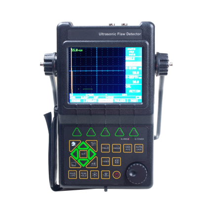
GAOTek Flaw Detector with Li Battery (100 Independent Set up) is used for quality controlling and to diagnose defects such as crack, inclusion and pinhole in a workpiece without destruction. This device allows you to work continuously for up to 8 hours. Gate and DAC alarm, high-speed capture, very low noise, and powerful PC software are some of its most important features. This flaw detector can be widely used in fields that need quality controlling and defect inspection such as chemical industry, metalworking, iron and steel metallurgical industry and manufacturing industry. In addition, it can be used in service-life evaluation and the active safety inspection in such fields as boiler pressure vessels, railway transportation and aerospace.
Features
- 100 independent set-up, any criterion can be input freely
- Li battery, can continuously be used up to 8 hours
- Big memory of 500 A graph
- Automated calibration of transducer Zero Offset and/or Velocity
- Gate and DAC alarm; Acoustic-optical alarm
- Automated switch three staff gauge
- Automated gain, Peak Hold and Peak Memory
- USB port, communication with PC is easy
- High-speed capture and very low noise
- 6 dB DAC functions
- Provides high contrast viewing of the waveform from bright, direct sunlight to complete darkness and easy to read from all angles
- DAC, AVG, TCG, B Scan; Solid housing (IP 65)
- Two gates setting and alarm indication
- Powerful PC software and reports can be export to excel
- Lock and unlock function of system parameters
- Automated echo degree
- Angles and K-value
- Electronic clock calendar
- AWS D1.1
Technical Specifications
| Dynamic range | ≥34 dB |
| Frequency Range | 0.5 MHz~15 MHz |
| Gain adjustment | 0~110 dB |
| Working mode | Single probe (receiving and sending), double probe (one for receiving and another for sending), transmission (transmission probe) |
| Range of scanning | 0~393 in (0~10000 mm) |
| D-delay | -20 μs~+3400 μs |
| P-delay | 0.0~99.99 μs |
| MTLVEL | 1000 m/s~15000 m/s |
| Reject | 0 %~80 % of screen height, step: 1% |
| Alarm | Three modes, i.e. forbidden wave, loss wave and auto |
| Horizontal linear error | Not more than 0.2% in the scanning range |
| Vertical linear error | Vertical linear error is not more than 3% |
| Sensitivity leavings | ≥62 dB |
| A-Scan display area | Full screen or local A-Scan display freezing and de-freezing A-Scan filling |
| Standard communication interface with PC | USB |
| Power adaptor | Input 100 V~240 V/50 Hz~60 Hz
Output 9 V DC/1.5 A |
| Battery | Li battery 7.4 V 4800 mAh |
| Port Type | BNC/LEMO |
| Data Save | 500 A-Scan images (including setting of instrument) |
| Weight | 2.20 lbs (1.0 kg) |
| Working Humidity | 20 %~90 % |
| Working Temperature | -4 °F~122 °F (-20 ℃~50 ℃) |
Additional Information
Operation
Functional Keyboard
Keys of the device are included in three groups: Function group, usual key group and special function group.
Usual key group comprises 9 key:
Up, down, Left, Right, Gain, Cate, Next page, Range and Full screen. They are used for usual operating.
Special function group consists of 6 keys: Save, Auto gain, Zoom, measure display, peak memory and Dynamic record.
Function group consists of 7 keys: on/off key, Setting, Probe, Auto Calibrate, DAC/AVG, System Config and Freeze.
Using of Power Supply
The device can work with plug-in power supply (AC, DC adaptor) or battery. The detector will switch the power supply to adapter automatically when the power supply adapter is used.
The detector will switch the power supply to battery automatically when the power supply adapter is turned off. The batteries will be charged automatically when the device, which is equipped with battery, is power supplied with adapter.
Charging the Li Battery
You can charge the Li battery by using an external battery charger. The continuous charging time for Li (4.8Ah) battery is about 4 h~5 h.
Connecting the Probe
The probe shall be connected to the socket at top of the instrument casing. Both connector sockets, have different function, sending socket at left (with T mark) and receiving socket at right (with R mark) . With Single-Probe mode, the sending socket can be used only. When connecting a double-wafer (TR) probe (one wafer for sending, another for receiving) or two probes (one for sending, another for receiving), take care that the sending probe shall be connected to the sending socket and receiving probe to the receiving socket. Otherwise, it may result in loss or disorder echo waveform.
Starting the Instrument
Press ![]() , turn on the instrument. It will carry out Self test. After five seconds, the instrument come into operation mode.
, turn on the instrument. It will carry out Self test. After five seconds, the instrument come into operation mode.
Description about Screen Display

Three Display Modes of Device’s Screen
- A-scan at normal mode

- A-scan at Enlarged mode

- Manual B-scanning

Description about Symbols Displayed on Screen

In the fig left, echo amplitude H=84 %, depth to the reflector = 0.06 in (1.57 mm), surface distance= 0.98 in (25.14 mm), echo times is 2, start of range=0.0 mm, end of range= 1.57 in (40.0 mm)

In the fig left, echo amplitude (pixels) H=148, Angular distance= 1.08 in (27.68 mm).
Description about other symbols
| * | Freeze | Freeze state |
| ! | Communication | The instruments are communicating with PC. |
| |
Angular distance | distance from the incidence point to the reflector point |
| |
Depth to reflector | depth from the incidence point to the reflector point. |
| |
Surface distance | surface distance from the incidence point to the reflector point. |
| |
Echo amplitude | The amplitude value of max echo within the gate. |
| |
Edge sampling | It shows that the instrument is in “Edge sampling” mode, depth and angular distance is the measure value of the first echo which is above the gate and within the gate. |
| |
Peak sampling | It shows that the instrument is in “Peak sampling” mode, depth and angular distance is the measure value of the echo with the max amplitude within the gate. |
| P | Memory peaks | peaks memory function is enabled. |
| T | Making video | Dynamic Record function is enabled. |
| E | Operation error | Operation error last time. |
| |
Radian revise | Abscissa and measure result is revised according to radian. |
Basic Operation Way
Firstly, you can select all usual functions by shortcut key. You can select a functional group by Right/Left key and Next page; select certain function by up/down key and Enter (press the rotary knob); at this time, you can modify parameters of this current menu by the rotary knob. And for some functional menus, they are shared by two functions, when you have selected such a function, by pressing Enter, it can be shifted to another function.
Selection of Functions
User can select a functional group by Right/Left key; select certain function by up/down key.
Rough and Fine Adjustment of Functions
For some functions, rough and fine adjustment are available. By pressing down the corresponding Enter key, you can shift between these two adjusting modes. With a symbol “*” in front of the function item that means it is in fine adjustment mode.
The following are the functional items with optional rough and fine adjustment
Functions Functional Group
RANGE BASE
MTLVEL BASE
D-DELAY BASE
T-VALUE BASE
Description of functions and operation way
Adjustment of BASE Group
In the BASE functional group, users can adjust and set the functional items relative with the display range, including RANGE, MTLVEL, D-DELAY and T-VALUE. During the detection, the display range of screen is in great relation to the material of workpiece and probe’s nature. The workpiece material will influence the transmission velocity of ultrasonic wave.
Detection Range (RANGE)
It is to set the measuring range for screen display during detection
Range: 0 mm~10000 mm/0.1"~200"
If what selected currently is RANGE functional menu, then by pressing ![]() , it is allowed to shift between Rough and Fine adjustment.
, it is allowed to shift between Rough and Fine adjustment.
Rough adjustment: 0.09 in (2.5 mm), 0.19 in (5 mm), 0.39 in (10 mm), 0.78 in (20 mm), 1.18 in (30 mm), 1.57 in (40 mm), 1.96 in (50 mm), 2.36 in (60 mm), 2.75 in (70 mm), 3.14 in (80 mm), 3.54 in (90 mm), 3.93 in (100 mm), 5.90 in (150 mm), 7.87 in (200 mm), 9.84 in (250 mm), 11.81 in (300 mm), 13.77 in (350 mm), 15.74 in (400 mm), 17.71 in (450 mm), 19.68 in (500 mm), 23.62 in (600 mm), 27.55 in (700 mm), 31.49 in (800 mm), 35.43 in (900 mm), 39.37 in (1000 mm), 78.74 in (2000 mm), 118.11 in (3000 mm), 157.48 in (4000 mm), 196.85 in (5000 mm), 236.22 in (6000 mm)
Fine adjustment:
Range Step graduation
≤3.93 in (≤100.0 mm) 0.003 in (0.1 mm)
>3.93 in (>100 mm) 0.03 in (1 mm)
Operation:
- By <Next Page > key, switch the function page.
- By <range> key, select the functional menu for RANGE, and then adjust parameters for RANGE by the rotary knob.
- Users can shift the Rough and Fine adjusting mode by the <Enter> key.
Display starting point (D-DELAY)
Can set the pulse shift during detection, viz. D delay. By which, users are allowed to adjust the starting position for waveform, as well as adjusting the zero point of pulse, so as to make sure that it is at the surface or a starting face inside the workpiece. If the pulse has to be started from the surface of workpiece, D delay must be set to 0.
Range: -20 µs~3400 µs
Step: 0.1µs
Operation:
- Select BASE functional group By < range > key, and by up/down key, select the functional menu for D-DELAY, and then adjust parameters for D-DELAY by the rotary knob.
- Users can shift the Rough and Fine adjusting mode by the <Enter> key.
Material velocity (MTLVEL)
Users are allowed to set the transmission velocity of ultrasonic wave in workpiece.
Range: 1,000 m/s~15000 m/s or 0.0394 in/µs~0.3937 in/µs
If what selected currently is MTLVEL function menu, then by the key ![]() , it is allowed to shift between Rough and Fine adjustment.
, it is allowed to shift between Rough and Fine adjustment.
Rough adjustment:
2,260 m/s 0.089 in /µs Sound velocity of transverse wave in copper
2,730 m/s 0.107 in /µs Sound velocity of longitudinal wave in organic glass
3,080 m/s 0.121 in /µs Sound velocity of transverse wave in aluminum
3,230 m/s 0.127 in /µs Sound velocity of transverse wave in steel
4,700 m/s 0.185 in /µs Sound velocity of longitudinal wave in copper
5,900 m/s 0.233 in /µs Sound velocity of longitudinal wave in steel
6,300 m/s 0.248 in /µs Sound velocity of longitudinal wave in aluminum
Fine adjustment: Step is 1 m/s or 0.0001 in/µs
Operation:
- Select BASE functional group By < range > key, and by up/down key, select the functional menu for MTLVEL, and then adjust parameters for MTLVEL by the rotary knob.
- Users can shift the Rough and Fine adjusting mode by the <Enter> key.
Thickness of workpiece (T-VALUE)
It is to set the thickness of workpiece during detection.
Thickness range: 0.03 in~39.37 in (1 mm~1000 mm)
Rough and Fine adjustment can be switched by the <Enter> key.
Rough adjustment: 0.03 in (1 mm), 0.19 in (5 mm), 0.39 in (10 mm), 0.78 in (20 mm), 1.96 in (50 mm), 3.93 in (100 mm), 7.87 in (200 mm), 11.81 in (300 mm), 15.74 in (400 mm), 19.68 in (500 mm), 23.62 in (600 mm), 27.55 in (700 mm), 31.49 in (800 mm), 35.43 in (900 mm) and 39.37 in (1000 mm)
Fine adjustment: 0.003 in (0.1 mm) < 3.93 in (<100 mm)
0.03 in (1 mm) >3.93 in (>100 mm)
Operation:
- Select BASE functional group. By < range > key, and by up/down key, select the functional menu for T-VALUE, and then adjust parameters for T-VALUE by the rotary knob.
- Users can shift the Rough and Fine adjusting mode by the <Enter> key.
Adjustment of PROBE Group
With this functional group, it is allowed to adjust and set the functional items in relation to ultrasonic sending and receiving, including PROBE TYPE/ PROBE POS, ANGLE/K-VALUE, P-DELAY/ X-VALUE, X-COORD/ PART DIA
PROBE TYPE/ PROBE POS
This menu is multipurpose for setting probe type and probe pos. By the <Enter> key, shift between probe type and probe pos.
PROBE TYPE:
Setting of ultrasonic probe. If the current probe is an echo probe, then set it to single; if it is a double-wafer probe, set it to DUAL, and if it is a through transmission probe, set it to THRU.
Options: STRAIGHT: Single straight element transducers. Use connector acts as a transmitter (T)
ANGLE: Angle straight element transducers. Use connector acts as a transmitter (T)
DUAL: Dual element transducers. One connector acts as a transmitter (T), the other acts as a receiver (R).
THRU: Two separate transducers, typically on opposite sides of the test specimen. Use the T transducer connector as the transmitter. The R transducer connector is designated as the receiver.
Operation procedure:
Select PROBE functional group By < Probe > key, and by up/down key, select the functional menu for PROBE TYPE, and then adjust parameters for PROBE TYPE by the rotary knob.
PROBE POS:
Select position of probe when you detect a pipe。
Options: Outside surface: Probe is placed on the outside surface of pipe. Now the corrected d value shows the depth of the flaw from the outside surface of pipe. L value shows the distance between flaw and probe front edge follow outside surface.
Inside surface: Probe is placed on the inside surface of pipe. Now the corrected d value shows the depth of the flaw from the inside surface of pipe. L value shows the distance between flaw and probe front edge follow inside surface.
Operation:
- Select PROBE functional group By < Probe > key, and by up/down key, select the functional menu for PROBE POS, and then adjust parameters for PROBE POS by the rotary knob.
Probe Angle (ANGLE)/Probe K Value (K-VALUE)
ANGLE:
It is to adjust the angle of a probe.
Range: 0.0°~89.0°
Step: 0.1°
Operation:
- Select PROBE functional group By < Probe > key, and by up/down key, select the functional menu for ANGLE, and then adjust parameters for ANGLE by the rotary knob.
K-VALUE:
Range: 0.00~57.29
Step: 0.01
Operation:
- Select PROBE functional group By < Probe > key, and by up/down key, select the functional menu for K-VALUE, and then adjust parameters for K-VALUE by the rotary knob.
P-DELAY/ X-VALUE
This menu is multipurpose for setting p-delay and x-value. By the <Enter> key, shift between P-DELAY and X-VALUE.
P-DELAY:
Can set the zero point of probe during detection, viz. P Delay. It is necessary to compensate the delay in probe resulted from acoustic beam in the pitch interval from energy exchanger to workpiece by P Delay.
Range: 0 µs~99.99 µs
Step graduation: 0.01 µs
Operation:
- Select PROBE functional group By < Probe > key, and by up/down key, select the functional menu for P-DELAY, and then adjust parameters for P-DELAY by the rotary knob.
X-VALUE:
It is to set the front edge of probe.
Range: 0 in~1.96 in (0.00 mm~50.0 mm)
Step: 0.003 in (0.1 mm)
Operation:
- Select PROBE functional group By < Probe > key, and by up/down key, select the functional menu for X-VALUE, and then adjust parameters for X-VALUE by the rotary knob.
X-COORD/ PART DIA
This menu is multipurpose for setting X-COORD and PART DIA. By the <Enter> key , shift between X-COORD/ PART DIA.
X-COORD:
Coordinate mode means the definition of the horizontal coordinate line, including “S-PATH” “P-VAL” and “DEPTH”, when the refraction angle is not zero, the function above is effective, when it is zero, the coordinate is defined as S-PATH.
Options: S-PATH, P-VAL, DEPTH
Operation:
- Select PROBE functional group By < Probe > key, and by up/down key, select the functional menu for X-COORD, and then adjust parameters for X-COORD by the rotary knob.
PART DIA:
When you detect a pipe, you must input the outside diameter of part and thickness exactly. Part diameter is the outside diameter of pipe.
Range:0.19 in~196.85 in (5.0 mm~5000 mm)
Step:<3.93 in (<100 mm) 0.003 in (0.1 mm)
>3.93 in (>100 mm) 0.03 in (1.0 mm)
Operation:
Select PROBE functional group By < Probe > key, and by up/down key, select the functional menu for PART DIA, and then adjust parameters for PART DIA by the rotary knob.
Adjustment of setting
Setting Group is used for Operations of detection setting. It includes SETTING, COPY, SAVE/MODIFY, DELETE/CLEAR ALL
Adjustment of MEM Group
This is for adjusting the memorizing modes, calling out, deleting and saving the configured data and detection parameters. It includes such functional menus as DATA NO, RECALL, SAVE and DELETE.
Adjustment of GATE Group
It is used for adjustment of gate settings, including Gate logic, Gate alarm, Gate start, Gate width and Gate height.
Functions of gate during detection:
- To monitor whether the job has flaws in the set logic and range, if yes, it will alarm.
- To measure the position and size of flaw echo.