")
Description
Overview:
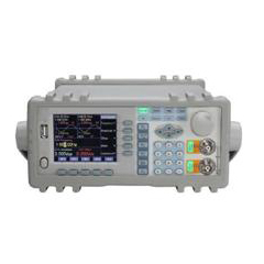
GAOTek DDS Function Generator with Arbitrary Waveform Function provides a sampling rate of 100 Msa/s, a vertical resolution of 8 bit and a waveform length of 1 kpts. Its output waveforms include 32 built-in waveforms and 8 sets of user defined waveforms. Its outstanding performance and system features make this function generator a perfect solution for your testing requirement.
Key Features:
- 5’’ TFT LCD display
- Modulations: FM, FSK, ASK, PSK
- Direct Digital Synthesis technology (DDS)
- Optional power amplifier
- output frequency 5 MHz/10 MHz/15 MHz/20 MHz
- 2 output channels
- output amplitude 1 mV (50 Ω) with good stability
- Sampling rate 100 MSa/s, vertical resolution 8 bit, waveform length 1024 points
- Arbitrary waveform function
- 32 built-in waveforms and 8 user-defined arbitrary waveforms
- 40 sets save & recall for panel settings
- Frequency sweep, amplitude sweep, burst and TTL output functions
- Over voltage, over current, short circuit and reverse voltage protections
- High speed rotary dial and keypad input
- Standard RS-232 interface for PC remote control
- Standard 200 MHz external frequency counter
Technical Specifications:
| Model | A0230008A | A0230008B | A0230008C | A0230008D | |||||||||
| Output frequency | 1 μHz-5 MHz | 1 μHz-10 MHz | 1 μHz-15 MHz | 1 μHz-20 MHz | |||||||||
| Waveform | |||||||||||||
| Output Waveform | 32 Built-in waveforms, including Sine, Square, Triangle, Ramp, Pulse, etc. | ||||||||||||
| 8 User-defined arbitrary waveforms. | |||||||||||||
| Waveform Length | 1024 Points | ||||||||||||
| Vertical Resolution | 8 Bits | ||||||||||||
| Sampling Rate | 100 MSa/s | ||||||||||||
| Sine | Harmonic Distortion | ≥ 40dBc (<1 MHz); ≥35dBc (1-20 MHz) | |||||||||||
| Total distortion | ≤ 1% (20 Hz-200 kHz) | ||||||||||||
| Square | Rise/fall time | ≤ 35 ns | |||||||||||
| Overshoot | ≤ 10 % | ||||||||||||
|
|
Duty cycle | 1 %-99 % | |||||||||||
| Frequency | |||||||||||||
| Range | Sine | 1 μHz-5 MHz | 1 μHz-10 MHz | 1 μHz-15MHz | 1 μHz-20 MHz | ||||||||
| Square | 1 μHz-5 MHz | ||||||||||||
| Other | 1 μHz-1 MHz | ||||||||||||
| Resolution | 1 μHz | ||||||||||||
| Accuracy | ±5 x 10⁻⁵ | ||||||||||||
| Stability | ±5 x 10⁻⁶ /3 hours | ||||||||||||
| Output Characteristics | |||||||||||||
| Amplitude | Range | 2 mVpp-20 Vpp (Open Circuit, ≤10 MHz) | |||||||||||
| 2 mVpp-15 Vpp (Open Circuit, 10 MHz-15 MHz) | |||||||||||||
| 2 mVpp-8 Vpp (Open Circuit, 15 MHz-20 MHz) | |||||||||||||
| Resolution | 20 mVpp (Amplitude>2 Vpp); 2 mVpp (Amplitude < 2 Vpp) | ||||||||||||
| Accuracy | ±(1 %+2 mVrms) (Open Circuit, 1 kHz, sine) | ||||||||||||
| Stability | ±0.5 % /3 hours | ||||||||||||
| Flatness | ±5 % (<10 MHz); ±10 % (>10 MHz) | ||||||||||||
| Output impedance | 50 Ω | ||||||||||||
| Offset | Range | ±10 V (Open Circuit, Attenuation 0 dB) | |||||||||||
| Resolution | 20 mVdc | ||||||||||||
| Accuracy | ±(1%+20 mVdc) | ||||||||||||
| Sweep | |||||||||||||
| Parameter | Frequency, Amplitude | ||||||||||||
| Range | Free to set start and stop point | ||||||||||||
| Time | 100 ms-900 s | ||||||||||||
| Direction | Up, Down, Up-Down | ||||||||||||
| Mode | Linearity, Logarithmic | ||||||||||||
| Control | Auto sweep or manual sweep | ||||||||||||
| Frequency Modulation (FM) | |||||||||||||
| Carrier Signal | CHA Signal | ||||||||||||
| Modulating Signal | CHB or External Signal | ||||||||||||
| Deviation | 0 % – 20 % | ||||||||||||
| Shift Keying | |||||||||||||
| FSK | Free to set the hop frequency and the carrier frequency | ||||||||||||
| ASK | Free to set the hop amplitude and the carrier amplitude | ||||||||||||
| PSK | Hop phase: 0-360°, resolution: 1° | ||||||||||||
| Alternative Rate | 10 ms-60 s | ||||||||||||
| Burst | |||||||||||||
| Carrier Signal | CHA Signal | ||||||||||||
| Trigger Signal | TTL_A Signal | ||||||||||||
| Burst Counts | 1-65000 Cycles | ||||||||||||
| Trigger Source | Internal TTL, External, Single | ||||||||||||
| CHB Output Characteristics | |||||||||||||
| Output Waveform | 32 Built-in waveforms, including Sine, Square, Triangle, Ramp, Pulse, etc. | ||||||||||||
| 8 User-defined arbitrary waveforms. | |||||||||||||
| Waveform Length | 1024 Points | ||||||||||||
| Vertical Resolution | 8 Bits | ||||||||||||
| Sampling Rate | 12.5 MSa/s | ||||||||||||
| Frequency Range | Sine: 1 μHz-1 MHz; Other: 1 μHz-100 kHz | ||||||||||||
| Frequency Resolution | 1 μHz | ||||||||||||
| Frequency Accuracy | ±1 x 10⁻⁵ | ||||||||||||
| Amplitude Range | 50m Vpp-20 Vpp (Open Circuit) | ||||||||||||
| Amplitude Resolution | 20m Vpp | ||||||||||||
| Output Impedance | 50 Ω | ||||||||||||
| CHB Signal is used as Burst Signal | |||||||||||||
| Carrier Signal | CHA Signal | ||||||||||||
| Trigger Signal | TTL_A Signal | ||||||||||||
| Burst Counts | 1-65000 Cycles | ||||||||||||
| Trigger Source | Internal TTL, External, Single | ||||||||||||
| TTL Output | |||||||||||||
| Waveform | Square, Rise/fall time ≤20 ns | ||||||||||||
| Frequency | 10 mHz-1 MHz | ||||||||||||
| Amplitude | TTL, CMOS compatible, low<0.3 V, high>4 V | ||||||||||||
| Power Amplifier (Optional) | |||||||||||||
| Max. output Power | 7 W (8 Ω), 1 W (50 Ω) | ||||||||||||
| Max. output Voltage | 22 Vpp | ||||||||||||
| Frequency Bandwidth | 1 Hz-200 kHz | ||||||||||||
| General | |||||||||||||
| Operation Characteristics | Key operation for all functions, menu display, rotary dial adjustment | ||||||||||||
| Display | 3.5 -inch TFT LCD | ||||||||||||
| Language | English, Chinese (Simplified), Chinese (Traditional) | ||||||||||||
| Interface | RS-232 Interface | ||||||||||||
| Operating Environment | 32 °F -104 °F, <80 % RH | ||||||||||||
| Power Source | AC110 V/220 V ±10 % selectable, 50/60 Hz, Max. 45 VA | ||||||||||||
| Dimension (W x H x D) | 10.2 in x 4.3 in x 15.15 in | ||||||||||||
| Weight | 6.6 lbs | ||||||||||||
Additional Information:
To operate this device below instructions have to follow:
- Menu Selection
If there is a triangle displayed on the right side of the menu, it means this menu has several options. Otherwise, this menu has only one option. This instrument has ten functions which are selected by the corresponding five function keys: [Channel], [Sweep], [MOD], [BURST], and [SK]. The selected option menu will change to green.
- Parameter Display
The area under the waveform display is for parameter display. The parameter display is divided into the five areas below:
“Frequency” area: display the frequency value or period value.
“Amplitude” area: display the output amplitude. Because of the frequently use of frequency and amplitude parameters, they are displayed in a larger font size to make them eye-catching.
“Offset and Other Parameters” area: display all parameters except the two important parameters.
The data units are shown on the bottom line of the TFT display. The units change according to the data characteristic. The input data have to be validated by pressing the corresponding one of the five blank soft keys.
“Parameter of Channel A” area: display the current waveform, function and the other parameters of the channel A.
“Parameter of Channel B” area: display the current waveform, function and the other parameters of the channel B.
- Numeric Keypad Input
If a parameter is selected, the color of this parameter changes to yellow, which means this parameter can be modified. There are ten numeric keys for data input. The input method is the shift input from left to right. The data can have one decimal point. If one data input has more than one decimal point, only the first one is valid.
In the offset mode, the negative sign can be input. After input a value, press a unit key to validate the input data.
If the input data has error, there are two ways to correct it. If the destination side of output signal can receive the wrong signal, press any unit key to terminate the previous operation.
- Knob Adjustment
The rotary knob is in use here. When a parameter is selected, the color of this parameter changes to yellow, and the color of one digit in this parameter changes to yellow too. Actually, this digit is located on the cursor position. Press key [<-] or [->] to move the cursor left or right. Rotate the knob to the right to continuously increase the digit on the cursor by one and make the carry to a higher unit position.
- Input Mode Selection
It is convenient to input the known data through the numeric keypad. It makes the input be set at only one step without the intermediate transition data. For the partial modification of the input data or at the situation of monitoring the variation process of the input data, the knob is usually more useful.
- Setup of Channel A
Press key [Channel] and select “CHAAlone” function.
Set the Frequency of Channel A
Select “Frequency” option by the corresponding soft key. The current frequency value changes to yellow. Use the numeric keypad or rotary knob to input a new frequency value.
Set the Period of Channel A
The frequency of channel A can also be set and displayed in the way of period. Select” Period” by the corresponding soft key. The current period value changes to yellow. Input a new period value here by numeric keypad or rotary knob.
Set the Amplitude of Channel A
Select “Amplitude” by the corresponding soft key. The current amplitude value changes to yellow. Input a new amplitude data here by numeric keypad or rotary dial.
The input and display of the Channel A amplitude value have two formats: Vpp and Vrms.
- Amplitude Attenuation
Press the corresponding “Offset” soft key twice to step down to “Attenuator”.
After instrument power on or reset, the attenuation is default in “AUTO” mode. In “AUTO” mode, the instrument automatically selects suitable attenuation ratio according to preset amplitude values.
- Output Load
The default amplitude value is calibrated when the output is open circuit. The real voltage on the output load is the default amplitude multiplying the dividing ratio of the load impedance and the output impedance. The output impedance of the instrument is about 50 Ω. When the load impedance is big enough and the voltage dividing ratio is close to 1, the loss on the output impedance can be ignored. The voltage on the output load is close to default amplitude value. When the load impedance is too small, the loss on the output impedance is significant and cannot be ignored. The voltage on the output load is not same as the default amplitude value. Please pay attention to this point.
The output of channel A has the over-voltage and over-current protections. The instrument cannot be damaged if the output is short-circuit only for a few minutes or the transient inverse voltage is less than 30V. However, this kind of operation should avoid in case of potential damage to the instrument.
- Amplitude Flatness
If the output frequency is lower than 1MHz, the amplitude and frequency characteristics of the output signal are very flat. If the output frequency is over 10MHz, due to the characteristics of the output amplitude and load matching, the amplitude and frequency characteristics of the output signal will not be so good.
- Set the Offset of Channel A
Select “Offset” by the corresponding soft key. The current offset value is shown on the TFT display. Enter a new offset data here by numeric keypad or rotary dial. The function generator outputs the desired signal at the CHA output.
- DC Voltage Output
If the amplitude attenuation is set at fixed 0dB, the output DC offset value is the preset offset value. Set the amplitude at 0V, the offset value can be set at any value within the range of ±10V. In this case, the function generator becomes a DC voltage source to output preset DC voltage signal.
- Select the Waveform of Channel A
The channel A can output 32 pre-stored waveforms and 8 user defined arbitrary waveforms, including: Sine, Square, Triangle, Pulse, Noise, Arbitrary waveforms. These waveforms can be directly selected by waveform keys. After selecting a waveform, the CHA output will output the selected waveform and display the waveform in display area of parameters of channel A.
- Set the Duty Cycle of Channel A
For the convenience of application, the duty cycle value can be input via numeric keypad or rotary dial.
- Set the Phase of Channel A
Press the corresponding soft key to step down to “Phase”. The phase value can be set at any value between 0~360° via numeric keypad or rotary dial.
Set the Output Impedance of Channel A
Select “Impedance” by the corresponding soft key. The impedance value changes to yellow.
- Setup of Channel B
Press key [Channel] to select “CHB Alone”. Setups for frequency, period, amplitude, waveform selection, duty ratio and phase apply the same procedures as explained in the setup of channel A. The difference is that there is no amplitude attenuation and no DC offset in channel B.
Set the Frequency of Channel B
Select “Frequency” by the corresponding soft key. The current frequency value changes to yellow, which means the frequency value can be modified and input via numeric keypad or rotary dial.
Set the Amplitude of Channel B
Select “Amplitude” by the corresponding soft key. The current amplitude value changes to yellow, which means the amplitude value can be modified and input via numeric keypad or rotary dial.
Select the Waveform of Channel B
The waveform of channel B is represented by the index number. Select “Waveform” by the corresponding soft key.
Set the Harmonic of Channel B
The frequency of channel B can be set and displayed as multiple times of channel A frequency. That is, channel B signal becomes the multiple N times harmonic of channel A signal. Select “B harmonic” by the corresponding soft key. Input harmonic times via numeric keypad or rotary dial.
Set the Phase of Channel B
Press the corresponding soft key to step down to “Phase”. The phase value can be set at any value between 0~360° via numeric keypad or rotary dial.
- Frequency Sweep
Press key [Sweep] and select “A SweepF” option. The function generator outputs the frequency sweep signal at the CHA Output. The sweep mode of output frequency is step sweep.
- Set the Start and Stop Frequency
The start point of frequency sweep is start frequency, and the stop point is stop frequency. To set the start frequency, press key “Start F” by the corresponding soft key and display the start frequency.
- Manual and Auto Sweep
After the “A SweepF” mode is selected, the sweep mode is default as manual mode. Select “Manual Sweep” by the corresponding soft key, the sweep process stops at once.
- Amplitude Sweep
Press key [Sweep] to select “A SweepA”. Settings of different sweep parameters, sweep mode, single sweep, and sweep monitor apply the same procedures as explained in section Channel A frequency sweep.
- Frequency Modulation (FM)
Press key [MOD] to select “CHA FM”. The function generator outputs the frequency modulation signal on the CHA Output.
- Set the Carrier Frequency
Select “Carrier Freq” by the corresponding soft key. The carrier frequency value changes to yellow. Input a new carrier frequency value here via numeric keypad or rotary dial.
- Set the Modulation Frequency
Select “MOD Freq” by the corresponding soft key. The modulation frequency value changes to yellow. Input a new modulation frequency value via numeric keypad or rotary dial.
- Set the Frequency Modulation Deviation
Select “FM Deviation” by the corresponding soft key. The frequency deviation value changes to yellow. Input a new deviation value here via numerical keypad or rotary dial.
- Set the Modulation Waveform
Since the signal of channel B as the modulation signal, the Channel B waveform is actually the modulated waveform. Select “MOD Wav” by the corresponding soft key. The index number changes to yellow. Input the correct index number by numeric keypad or rotary dial so as to select corresponding waveform.
- Set the Carrier Frequency
Select “Carrier Freq” by the corresponding soft key. The carrier frequency value changes to yellow. Input a new – 17 – carrier frequency value here via numeric keypad or rotary dial.
- Set the Hop Frequency
Select “Hop Freq” by the corresponding soft key. The hop frequency value changes to yellow. Input a new hop frequency value via numeric keypad or rotary dial.
- Set the Interval Time
Select “Interval” by the corresponding soft key. The interval time value changes to yellow. Input a new interval time via numeric keypad or rotary dial.
- PSK Observation
Due to the phase variation caused by PSK signal, it is hard to have synchronization on the oscilloscope, and therefore cannot observe a stable waveform. If the frequency of the channel B is set at the same value of carrier frequency, and use channel B signal as synchronization burst signal, a stable PSK signal waveform can be observed.
- Burst Output of Channel A
Press key [Channel] to select “CHA Alone”, then press key “Burst” to go to channel A burst mode. The TFT will display “CHA Burst” in the upper portion.
- Set the Carrier Frequency
Signal of channel A is used as the output burst signal. Therefore, channel A signal frequency and amplitude should be firstly set up. Select “Carrier Freq” by the corresponding soft key. The carrier frequency value becomes yellow. Input a new carrier frequency value here via numeric keypad or rotary dial.
- Set the Carrier Amplitude
Select “Carrier Amp” by the corresponding soft key. The carrier amplitude value becomes yellow. Input a new carrier amplitude value here via numeric keypad or rotary dial.
- Set the Burst Count
Select “Cycles” by the corresponding soft key. The burst count value becomes yellow. Input a new burst count number here via numeric keypad or rotary dial.
- Set the Burst Frequency
Select “Burst Freq” by the corresponding soft key. The burst frequency changes to yellow. Input a new burst frequency here via numeric keypad or rotary dial.
- Set the Single Burst Mode
Press the soft key corresponding to “TTL_A Trig” to step down to “Single” to enter single burst mode. The function generator turns off the continuous burst mode and signal output. In the single burst mode, press key [CHA Output/Trigger] once, the burst process executes once and the function generator outputs one burst waveform according to the preset value of the burst count.
- Set TTL_A Burst
Select “TTL_A Burst” by the corresponding soft key. At the rise edge of every TTL_A signal, the burst process executes once, and the instrument outputs a set of preset numbers of burst waveform according to the preset burst count number. The burst process is operating continuously.
- Set External Burst
Press the soft key corresponding to “TTL_A Burst” to step down to “EXT Burst” to enter external burst mode. Input external burst signal from the “Count In” terminal on the rear panel. To validate “Count In” function, the generator must have frequency counter input.
Burst count function can be used to test the dynamic features of audio equipments as well as to calibrate a counter.
- Burst Output of Channel B
Press key [Channel] to select “CHB Alone”. Next press key [Burst] to enter “CHB Burst” mode. The function generator outputs a waveform with a specified number of cycles at the burst frequency continuously at the CHB Output. Each set has a preset burst count and there is a time interval between each burst. Parameter settings of channel B burst is the same as setting procedure of channel A burst parameter settings.
- Set the Burst Frequency
Select “Burst Freq” by the corresponding soft key. The burst frequency changes to yellow. Input a new burst frequency here via numeric keypad or rotary dial. In channel B burst operation, TTL_B signal is used as the burst signal. The burst frequency actually is the TTL_B frequency. The burst frequency is determined by the values of the Channel B frequency and the burst count.
- TTL Output
Press key [TTL] to enable the TTL function. The upper-left portion of the TFT displays TTL, and there is TTL signal output at the TTL_A and TTL_B terminals on the rear panel.
- Set the TTL_A Frequency
Select “TTL_A Freq” by the corresponding soft key. The TFT displays TTL_A frequency value. A new TTL_A frequency value can be set here via numeric keypad or rotary dial.
- Set the TTL_A Duty Cycle
Press soft key corresponding to “TTL_A Duty”. The TFT displays TTL_A duty ratio value. A new duty ratio value can be set here via numeric keypad or rotary dial.
- Set the TTL_B Frequency
Select “TTL_B Freq” by the corresponding soft key. The TFT displays TTL_B frequency value. A new TTL_B frequency value can be set here via numeric keypad or rotary dial.
- Set the TTL_B Duty Cycle
Select “TTL_B Duty” by the corresponding soft key. The TFT displays TTL_B duty ratio. A new TTL_B duty ratio value can be set here via numeric keypad or rotary dial.
Measure External Frequency
Press key [COUNT] to select “Measure Freq” option by the corresponding soft key. The TFT display shows the external measurement interface. In this mode, the instrument is a frequency meter and measures the frequency value of the external signal.
- Self-Check and Demonstration
The instrument is capable of using internal waveform to carry out self check and present demonstration. Use a test cable to connect the CHA terminal with the “Count In” terminal on the rear panel. Select “Measure Freq” by the corresponding soft key.
- Measure External Frequency
Select “Measure Freq” by the corresponding soft key. Input the external frequency from the “Count In” terminal on the rear panel.
- Set the Gate Time
Select “Strobe Time” by the corresponding soft key. The gate time changes to yellow. Input a new gate time data here by numeric keypad or rotary dial.
- System Setup
Press key [Utility] to enter system setup mode. The system interface is displayed. Users can store or recall system setup parameters and carry out the programmable interface operation.
- Store Parameters
Select “Store” by the corresponding soft key. All preset parameters can be stored into the memory of the instrument.
- Recall Parameters
Select “Recall” by the corresponding soft key. Input recall index number 0 to 39 to recall the stored settings in each memory. Input number 0 recalls the default parameter setting of the instrument. After the parameters are recalled, the instrument outputs the signal based on the recalled parameters.
- Remote Address
Select “Address” by the corresponding soft key. The remote address changes to yellow. The remote address can be entered by numeric keypad or rotary dial
- Beeper
Select “Beep On” by the corresponding soft key. The beeper can be turned on or off here.
- Choose a Language
Select a language by the corresponding soft key. There are three languages available in the system: English, Chinese (simplified), Chinese (traditional).