Description
Overview
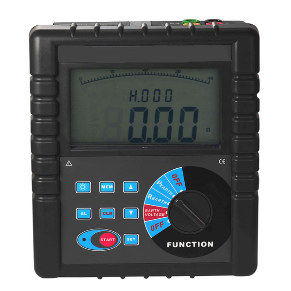
GAOTek Earth Resistance Tester with 2, 3 and 4-Pole Measurement Testing is specially designed and manufactured for the measurement of earth resistance, soil resistivity, earth voltage, and AC voltage. It adopts the latest digital and micro-processing technology, specifically, 4-pole, 3-pole and simple 2-pole measurement method for earth resistance measurement, importing FFT and AFC technology.
The unique functions of anti-interference capability, ability to adapt to the environment and consistency of repeat testing makes it capable of high precision, high stable and reliable for prolonged measurement. It is widely used in electric power, telecommunications, meteorology, oil field, construction, lightning protection, industrial electrical equipment and other earth resistance, soil resistivity, earth voltage, AC voltage measurement.
Key Features
- 4-digit large LCD display, blue screen backlight suitable to work in dim light places.
- Measurement of earth resistance, soil resistivity, earth voltage, and AC voltage.
- 2-pole, 3-pole, and 4-pole earth resistance measurement mode.
- 300 sets of data storage.
- LED flash indicator, LCD count down display, and progress bar indicator.
- Alarm setting; Data lock and storage function; Data reading and deletion function.
- Recognize interference signal automatically.
- RS232 interface for data monitoring through software; storage data can be uploaded and saved to computer.
- Replaceable Zi-Mn dry battery, 300 hr continuous standby time.
Applications
- Measurement of earth resistance
- Measurement of soil resistivity
- Measurement of AC voltage
- Used in electric power, telecommunications, meteorology, oil field, construction, lightning protection, industrial electrical equipment and other earth resistance, soil resistivity, earth voltage, AC voltage measurement
Technical Specifications
| General Specification | |
| Function | Measurement of 2/3/4-pole earth resistance, soil resistivity, earth voltage, AC voltage |
| Power Supply | DC 9 V (Zi-Mn dry battery R14S 1.5 V 6 Pcs, continuous standby for 300 hours) |
| Measurement Range | Earth Resistance: 0.00 Ω-30.00 kΩ |
| Soil Resistivity: 0.00 Ωm-9000 kΩm | |
| Measuring Mode | 4-pole measurement, 3-pole measurement, simple 2-pole measurement |
| Measuring Method | Earth Resistance: rated current change-pole method, measurement current 20 mA Max
Soil Resistivity: 4-pole measurement (Wenner method) Earth Voltage: average rectification(between P(S)-ES |
| Test Frequency | 128 Hz / 111 Hz / 105 Hz / 94 Hz (AFC) |
| Short-circuit Test Current | AC 20 mA max |
| Open-circuit Test Current | AC 40 V max |
| Test Voltage Wave | Sine wave |
| Electrode Distance Range | Can be set 1 m-100 m |
| Shift | Earth Resistance: 0.00 Ω-30.00 kΩ, automatic shift |
| Soil Resistivity: 0.00 Ωm-9000 kΩm, automatic shift | |
| Backlight | Blue screen backlight, suitable for dim light places |
| Display Mode | 4-digital large LCD display, blue screen backlight |
| Measuring Indicator | LED flash indicator, LCD count down display, progress bar indicator |
| LCD Frame Dimension | 5.03 in × 2.95 in (128 mm × 75 mm) |
| LCD Window | 4.88 in × 2.63 in (124 mm × 67 mm) |
| Standard Test Wire | 4 wires: red 20 m, black 20 m, yellow 10 m, and green 10 m |
| Simple Test Wire | 2 wires: red 1.6 m and black 1.6 m |
| Auxiliary Earthing Rod | 4 rods: Φ 0.39 in × 5.90 in (10 mm × 150 mm) |
| Measuring Rate | Earth voltage: about 3 times/second |
| Earth resistance, soil resistivity: about 5 seconds/time | |
| Measuring Times | Over 5000 times (Short-circuit test, interval time should be at least 30 seconds) |
| Line Voltage | below AC 600 V |
| RS232 Interface | Possess RS232 interface, software supervision, storage data can be uploaded to computer, saved or printed. |
| Communication Wire | RS232 communication wire, with length 1.5 m |
| Data Storage | 300 sets, “MEM” icon storage indicator, flash display “FULL” icon to indicate storage is full |
| Data Hold | Data hold function: “HOLD” icon display |
| Data Access | Data read function: “READ” icon display |
| Overflow Display | Exceeding measuring range overflow function: “OL” icon display |
| Interference Test | Recognize interference signal automatically, “NOISE” icon display when interference voltage exceed 5 V |
| Auxiliary
Earthing Test |
Can measure auxiliary earth resistance, 0.00 KΩ-30 kΩ (100 R + rC < 50 kΩ, 100 R + rP < 50 kΩ) |
| Alarm Function | When measuring value exceeds alarm setting value, there is “Toot-toot-toot” alarm hint |
| Overload Protection | Measuring earth resistance: between each interfaces of C(H)-E, P(S)-ES, AC 280V/3 seconds |
| Insulation Resistance | Over 20MΩ (between circuit and enclosure it is 500V) |
| Withstanding Voltage | AC 3700V/rms (Between circuit and enclosure) |
| Electromagnetic Features | IEC61326(EMC) |
| Protection Type | IEC61010-1 (CAT Ⅲ 300V, CAT IV 150V, Pollution 2),
IEC61010-031, IEC61557-1 (Earth resistance), IEC61557-5 (Soil resistivity), JJG 366-2004 |
| Power Consumption | Standby: approx 20 mA (Backlight shut off) |
| Boot and with backlight: approx 45 mA (25 mA without backlight) | |
| Measurement: approx 100 mA (Backlight shut off) | |
| Working Temperature & Humidity | 14 ℉ – 104 ℉ (-10 ℃-40 ℃), below 80% RH |
| Storage temperature & humidity | -4 ℉-140 ℉ (-20 ℃-60 ℃), below 70% RH |
| Dimension (L×W×H) | 8.46 in × 7.48 in × 3.74 in (215 mm × 190 mm × 95 mm) |
| Weight | Total weight: 9.92 lbs (4.5 kg) (including package) |
| Tester: 3.181 lbs (1443 g) (including battery) | |
| Testing wires: 3.43 lbs (1560 g) | |
| Auxiliary earthing rods: 2.06 lbs (935 g) (4 pcs) | |
|
Base Conditions and Working Conditions |
|||
| Influence Quantity | Base Condition | Working Conditions | Remark |
| Ambient Temp | 73.4 ℉±33.8 ℉ (23 ℃ ± 1 ℃) | 14 ℉-104 ℉ (-10 ℃-40 ℃) | —- |
| Ambient Humidity | 40%-60% | 40%-60% | —- |
| Working Voltage | 9 V±0.1 V | 9 V±1.5 V | rC, rP |
| Auxiliary Earth Resistance | <100 Ω | <30 kΩ | —- |
| Interference Voltage | no | <20 V | —- |
| Interference Current | no | <2 A | —- |
| Electrode Distance when measuring R | a>5 d | a>5 d | —- |
| Electrode Distance when measuring ρ | a>20 h | a>20 h | —- |
| Intrinsic error and performance indicators under base conditions | |||
| Category | Measurement Range | Intrinsic Error | Resolution |
| Earth Resistance (R) | 0.00 Ω – 30.00 Ω | ±2% rdg ± 3 dgt | 0.01 Ω |
| 30.0 Ω – 300.0 Ω | ±2% rdg ± 3 dgt | 0.1 Ω | |
| 300 Ω – 3000 Ω | ±2% rdg ± 3 dgt | 1 Ω | |
| 3.00 kΩ – 30.00 kΩ | ±4% rdg ± 3 dgt | 10 Ω | |
| Soil Resistivity (ρ)
|
0.00 Ωm – 99.99 Ωm | According to the precision of R (ρ=2πaR; a:1 m-100m, π=3.14) | 0.01 Ωm |
| 100.0 Ωm – 999.9 Ωm | 0.1 Ωm | ||
| 1000 Ωm – 9999 Ωm | 1 Ωm | ||
| 10.00 kΩm – 99.99 kΩm | 10 Ωm | ||
| 100.0 kΩm – 999.9 kΩm | 100 Ωm | ||
| 1000 kΩm – 9000 kΩm | 1 kΩm | ||
| Earth Voltage | ±2% rdg ±3 dgt | ±2% rdg ±3 dgt | 0.1 V |
Packaging List
| Sr. No. | Item Description | Quantity |
| 1 | GAOTek Earth Resistance Test unit | 1 |
| 2 | Tester Bag | 1 |
| 3 | Auxiliary Earthing Rod | 4 |
| 4 | Standard testing wire (4 wires: Red 20 m, Black
20 m, Yellow 10 m, and Green 10 m) |
4 |
| 5 | Simple testing wire (2 wires: Red 1.6 m and Black 1.6 m) | 2 |
| 6 | Zinc-manganese Dry Battery (R14S 1.5 V) | 6 |
| 7 | Monitoring Software Disk | 1 |
| 8 | RS232 Communication Cable | 1 |
| 9 | Manual/Warranty Card/Qualification Certificate | 1 |
Additional Information
Product Description

- LCD
- Button area
- Rotary switch for selecting function
- RS232 interface
- Interface of testing wires
- P(S) interface: Voltage electrode
- C(H) interface: Current electrode
- E interface: Earth electrode
- ES interface: Auxiliary earth electrode
- Standard test wires
- Auxiliary earthing rods
- Simple test wires
LCD Display

- Progress bar (Dynamic display the progress of testing)
- Alarm symbol (Display when open alarm function, flash when exceed the alarm value)
- Exceed voltage symbol (Display when the measured voltage exceed 30 V, please pay attention to the safety)
- AC symbol
- Data hold symbol (Display when press MEM to hold data)
- Data access symbol (Display when long press MEM for at least 3 seconds to access data)
- Data storage symbol (Display when press MEM to hold data and store)
- Interference signal symbol (Display when the interference voltage exceeds 5V)
- Low battery symbol (Display when the battery voltage decreases to 7.5 V)
- Display the group number of stored data, and display countdown.
- Interference electrode symbol (Display when the electrode exceeds 5 V interference voltage)
- Measured data
- Voltage unit symbol
- Resistance, soil resistivity, length unit symbol (Ω, kΩ, Ωm, kΩm, m)
Operation Methods
Switch On/Off
Rotate FUNCTION rotary switch to fulfill switch on and off. When rotary switch button displays
“OFF” for shut-off. The Tester has no auto shut-off function, so please shut it off after usage in case of battery consumption saving.
Battery Voltage Check
After switch on, if LCD displays low battery voltage icon “![]() ” which indicates that battery voltage is low, and please replace the battery in compliance with instructions. Adequate battery power can ensure the accuracy of measurement.
” which indicates that battery voltage is low, and please replace the battery in compliance with instructions. Adequate battery power can ensure the accuracy of measurement.
AC Voltage Measurement
|
|
Ac line voltage measurement can’t exceed 600 V. |
| Connect P(S) and ES interface to test commercial AC voltage, no need to connect C(H) and E interface. |
AC voltage measurement refers to the general commercial AC voltage measurement, pay attention to the difference between earthing voltage, the meter can be used for testing below 600V AC line voltage.
As shown below: Firstly, connect test wires with P(S), ES interface, secondly connect test wires with tested line, then rotate FUNCTION rotary switch to “EARTH VOLTAGE” and start testing, LCD will display the test results.

Earth Voltage Measurement
|
|
Earth voltage measurement need to use one auxiliary earthing rod. |
| The meter connects with the earth only by testing wires and auxiliary earthing rods. Other testing wires of meter’s interface can’t connect with commercial power line L, N, otherwise may cause leakage, the breaker may start, it is dangerous. | |
| Earth voltage measurement can’t exceed 600 V. |
Earth voltage: That is a potential differences between zero potential differences and earthing equipment shell, earthing wires, earthing body when electrical equipment has a earthing fault. Earth voltage is the potential differences between the earth. As a reference point, the earth is zero potential.
Earth voltage measurement need to use one auxiliary earthing rod. Please pay attention to the difference from commercial AC voltage measurement. As shown below: meter, auxiliary earthing rods, testing wires are all connected, rotate FUNCTION rotary switch to “EARTH VOLTAGE” and start testing, LCD will display the test results.

4-wires Precise Earth Resistance Measurement
|
|
In the testing of earth resistance, should firstly confirm the earth voltage of earthing wire, the voltage between C(H) and E or P(s) and ES must under 20V, the meter showing NOISE symbols when the earth voltage exceeds 5V, and the measured value of earth resistance may produce error. At this time, firstly interrupt power supply to earthing equipment, make sure the earth voltage decreases, and then test earth resistance again.
|
4-wires measurement: The 4-wires method can eliminate influence of contact resistance (usually result from dirty or rusty) between measured earthing body, auxiliary earthing rods, test clips, meter’s input interface. The 4-wires method can also eliminate influence of line resistance. So it is better than 3-wires measurement.
As shown below: Start from the measured body, interval 5m-20m, respectively insert P(S), C(H) auxiliary earthing rods deep into the earth in a straight line, and then connect testing wires (black, green, yellow, red) from E, ES, P(S), C(H) interfaces corresponding to measured earth electrode E, auxiliary voltage electrode P(S), auxiliary current electrode C(H).
|
|
The distance from measured earthing body to current electrode C(H), should at least five times longer than the embedded depth of measured earthing body, or the embedded electrode depth (d). |
| When measuring the total earth resistance of complex earthing system, d is the length of the biggest diagonal line of this earthing system. | |
| Testing wires can’t be winded together, or may affect the measuring accuracy. |

3-Wires Earth Resistance Measurement
3-wires measurement: As shown below, short-circuit ES and S interface, which is 3-wires measurement. The operation of meter is the same with 4-wires measurement. The 3-wires method can’t eliminate influence of line resistance, also can’t eliminate influence of contact resistance between meter and testing wires, testing wires and auxiliary earthing rods. Meanwhile, oxidation layer on measured earthing body must be removed when measuring.

2-Wires Simple Measurement
2-wires method: This method is a simple method for measurement that does not use auxiliary earthing rod, taking the earth electrode with the minimal existing earth ground resistance value as auxiliary earth electrode, and connecting by two simple testing wires (in which C(H)–P(S), E–ES interfaces are in short circuit). It can make use of metal pipes, fire hydrants and other metal buried objects, common earthing of commercial electric power system or lightning protection earth ground electrode and others to replace auxiliary earthing rods C(H),P(S), and pay attention to remove oxide layer on the connection point of the selected metal auxiliary earthing object when making measurement.
Wire connection is as following figure, and refer to 4-wires measurement for other operations.

2-wires simple method for measurement of earth ground resistance, its reading on tester is the total value of earth ground resistance value of measured earthing object and that of commercial earthing object, that is:
R=RX+re
In which:
R is the tester reading value;
RX is the earth ground resistance value of measured earthing object; re is the earth ground resistance value of common earthing object like commercial use power system.
Then, the earth ground resistance value of measured earthing object
is: RX=R-re
Soil Resistivity Measurement
Soil resistivity is measured by 4-pole method (Wenner method)
4-pole method (Wenner method): Connect testing wires as shown below, pay attention to the distance between auxiliary earthing rods, and the embedding depth. Respectively insert C(H), P(S), ES, E auxiliary earthing rods deep into the earth in a straight line, and then connect testing wires (red, yellow, green, black) corresponding to C(H), P(S), ES, E of interfaces and measured auxiliary earthing rods.

Data Upload
The stored data can be uploaded to computer. Make good connection of computer with RS232 communication wire of the tester, switch on the tester and run monitoring software, and if the software displays that interface is open and the connection is successful, then it can read the stored historical data, upload to company and preserve.
Monitoring software has the function of online real-time monitoring and historical inquiry, dynamic display, with alarm value settings and alarm indicator, and the function of historical data access, reading, preserve, print and other functions.
Battery Replacement
|
|
Please don’t replace battery in flammable spot |
| Please don’t replace battery during measurement | |
| Pay attention to battery polarity and specification, and don’t mix use of new and used battery to avoid damage on tester | |
| When the enclosure of Tester is wet, please do not open battery cover | |
| Please put the used batteries in appointed collection place |
- Switch off; making sure that the Tester is under switch-off state.
- Loosen the four screws on battery cover at the bottom of the Tester, and open battery cover.
- Replace new battery, pay attention to battery polarity and specification, close battery cover, and fasten screw.
- Switch on verification, otherwise re-operate.


