


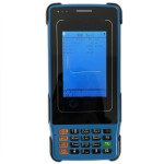
Description
Features
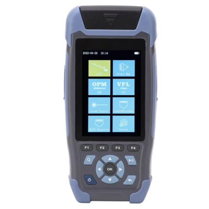
- 320 x 480 3.5 in (8.89 cm) LCD
- Test objects: ADSL; ADSL2; ADSL2+
- READSL; VDSL2 (30 a, 35 b profile is optional)
- Fast Copper tests with DMM
- (ACV, DCV, Loop and Insulation Resistance
- Capacitance, Distance)
- Support VLAN, Vectoring
- Compliant with all known DSLAMs
- Supports Modem emulation
- simulating login to Interne
- Supports ISP login (username or password)
- IP Ping test (WAN PING Test, LAN PING Test)
- Rechargeable Li ion Battery
- Support optical power meter, VFL function
- Support cable tracing, check line sequence,
- landline telephone function
- Support cable fault locator (TDR) function
Technical Specifications
| xDSL test main functions | Physical Layer Info PPPoP Dial FTP Client, Fixative IP Network Layer Test Modem Emulation PING Support VLAN, HLOG,QLN Error Code Statistics Bit Graph Display BPT or SNR Data Modem Parameter Setting (VPI/VCI) |
| Standards | ITU G.994.1 (G.hs), ITU G.992.5, ITU G.992.5 Annex L. The max distance which can be connected is 6.5km. Be compatible with ADSL, ADSL2 and READSL. |
| Attenuation: | 0 dB to 63.5 dB |
| Noise margin | 0 dB to 32 dB |
| Upstream Channel Rate (interweaved or fast mode) | 0 Mbps to 1.2 Mbps |
| Downstream Channel Rate (interweaved or fast mode) | 0 Mbps to 24 Mbps |
| The modulating bits in the DMT sub-channel | 0 to 15 and each sub-channels’ frequency points |
| The number of error codes | CRC, HEC, FEC, NCD, OCD |
|
Other Parameters |
The output power of DSL
It can display every condition of the DSL line: lost signal and shutdown of link |
| Standards | ITU G.993.2(VDSL2). Be compatible with ADSL2+, ADSL standard. |
| Upstream Channel Rate (interweaved or fast mode) | 0 to 100 M |
| Downstream Channel Rate (interweaved or fast mode) | 0 to 100 M |
| The modulating bits in the DMT sub-channel | 0 to 15 and each sub-channels’ frequency points |
| The number of error codes | CRC, HEC, FEC, NCD, OCD |
|
Other Parameters |
The output power of DSL It can display every condition of the DSL line: lost signal and shutdown of link DSLAM information Error seconds INP pulse protection SNR channel figure Channel noise margin figure |
| Support profiles | Profile 8 a, 8 b, 8 c, 8 d, 12 a, 12 b, 17 a,30 a (optional),35 b (optional) |
| DC Voltage | -400 V to 400 V; Resolution: 0.1 V |
| AC Voltage | 0 to 290 V |
| Capacitance | 0 to 1000 nF; Accuracy: 0 to 10 nF: ±2 nF, 10 nF to 1000 nF: ±2 %±2 nF |
| Loop Resistance | 0 to 20 KΩ; Accuracy: 0 to 100: ±3 %±4 Ω, 100 to 500: ±3 %, 500 to 20 KΩ: ±2 % |
| Insulation Resistance | 0 to 50 MΩ; Accuracy: 0 to 1.0M: ±0.1 MΩ, 1.0 to 30 M: ±10 %±0.5 MΩ |
| General specifications | Check line mix and break fault.
Auto and manual distance test |
| Test Range | 2.48 mi, 4.97 mi (4 km, 8 km) is optional) |
| Highest resolution | 3.2 ft (1 m) |
| Dead Zone | 0 ft (0 m) |
| Power consumption | 1 W |
| VOP Adjusting range | 100 to 300 m or us |
| Distance test accuracy | ≤3.2 ft (1 m) |
| Pulse test voltage range | ≥30 V |
| Test cable type | Network cable, twisted pair cable, telephone line, USB cable, coaxial cable. |
| Line status test | Determine open or short circuit |
| Voltage polarity detection | Positive and negative of DC voltage |
| Distance of signal transmission | No less than 1.86 mi (3 km) |
| DC Voltage | No more than 48 V |
| Function | Support generates network line signal to view the network check line sequence with the receiver |
| Feature | Easy to operate determine the line sequence by receiving side lights order |
| Wavelength range(nm) | 800 nm to 1700 nm |
| Photo sensing material | InGaAs |
| Power test range(dBm) | -70 dBm to +10 dBm or -50 dBm to +26 dBm |
| Error range | ±5 % |
| Display distinguishability | Linear display: 0.1 %; logarithmic display: 0.01 dBm |
| Adapters | 0.09 in (2.5 mm) universal adapter |
| VFL | FP to LD |
| Wavelength | 650 nm ± 20 nm |
| Output power | 5 mw (10 mw or 20 mw optional) |
| Connector | 0.09 in (2.5 mm) universal adapter |
| Working mode | CW or 2Hz modulation |
| Applicable fiber | SM or MM |