Description
Overview
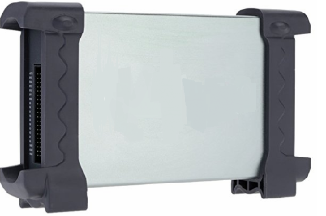
GAOTek Logic Analyzer (150 MHz/32 Ch/2 G Memory) is a 32-channel device which combines the function of logic analyzer, bus analyzer, and logic probe in one device and is used to analyze, test and troubleshoot digital circuits. It operates in the frequency of 150 MHz input bandwidth with 2G bit memory depth. The use of integrated USB 2.0, advanced large-scale integrated circuits, high-frequency digital circuitry, FPGA, CPLD, and other advanced technology, make the logic analyzer to be portable, and easy-to-use. It has a sufficient number of input channels and can simultaneously observe a lot of information or data flow direction control information, and can capture narrow pulse interference. This instrument is suitable for teaching assistants, college students in scientific research and development, and electronic measurement engineers.
Features
- The device combines the function of a logic analyzer, bus analyzer, and logic probe etc. in one.
- Suitable for various digital circuits development, testing, analysis and debug, is an able aider for electronics development & electronic measuring engineers, and teaching and research work at the college.
- Supports 2G bit memory depth (DDR2), 400 MSa/s sampling rate, and 150 MHz bandwidth.
- The innovative trigger mode and new analysis measurement tool makes the measurement simple and efficient.
- It can set the edge, level, bus, data width etc. Trigger mode, easy to use.
- Its innovative data analysis function makes your analysis UART, SPI, and I2C etc. data easier and relax.
- The strong protocol secondary analytic capability is able to export files in CSV, TXT, DOC format, which facilitates secondary analysis with other tools.
- Plug and play high-speed USB 2.0 interface.
- Excellent industrial design, similar interface to digital storage oscilloscope, easy to use.
Technical Specifications
Channel | 32 |
Input Voltage Range | -6 V ~ 60 V |
Input Impedance | 200 K(C=10 p) |
Maximum Input Signal Bandwidth | 150 MHz |
Maximum Sample Rate | 400 MHz |
Voltage Threshold Range | -6 V ~ 6 V |
Minimum Time Resolution | 2.5 ns |
Sample Depth | 64 M Sample |
Memory Depth | 2G bits |
Compatible Input | TTL, LVTTL, CMOS, LVCOMS, ECL, PECL, EIA |
Electrostatic Protected Area | 15 KV |
Interface | USB Port |
Voltage Range | 4.5 V ~ 5.5 V |
Maximum Power | 3.5 W |
Operating System | Win XP/2000/Win7 |
Size | 8.14 in x 1.45 in x 4.84 in (207 mm x 37 mm x 123 mm) |
Weight | 0.85 lbs (390 g) |
Operating Temperature Range | 14 °F~140 °F (-10 °C ~ 60 °C) |
Storage Temperature Range | -40 °F~140 °F (-40 °C~60 °C) |
Additional Information
Accessories:
- GAOTek Logic Analyzer
- Cable
- Test Hook
- USB Cord
- 5 V Power Adaptor
Block Diagram
System Requirements
Minimum System Requirements Operating System
Windows XP/Vista/Win 7
Memory
128MB
Graphic Card
Microsoft DirectX supported
Screen resolution: 1024×768
Color depth: 16 bit
Installing Software
- While in Windows, insert the installation CD into the CD-ROM drive.
- The installation should start up automatically. Otherwise, in Windows Explorer, switch to the CD-ROM drive and run “Setup.exe”.
- The device Installation is started. Click ‘Next’ to continue.
- Choose a destination directory. Click ‘Next’ to continue.
- Check the setup information. Click Next to start copying of files.
- This status dialog is displayed during copying of files.
- Updating your System Configuration.
- The installation is complete.
User Interface
The device provides users with a simple and full-featured interface so that users needn’t spend a lot of time to learn.At the same time, it provides control panel, waveform panel, bus panel, measurement panel, and trigger panel.
File
- Export As CSV File: Export data to file as “CSV”
- Export As TXT File: Export data to file as “TXT”
- Export As BMP File: Export data to file as “BMP”
- Print…: Print the current waveform
- Print Preview: Preview the current waveform
- Print Setup: Setup print type
- Exit: Exit the device
View
- Toolbar: Show or hide the toolbar window
- Status Bar: Show or hide the status window
- Control Window: Show or hide the control window
- Measure Window: Show or hide the measure window
- Zoom In: Enlargement waveform view
- Zoom Out: Reduction waveform view
- Zoom All: Show entire waveform view
Setup
- Signal Name Setup: Modify the signal name.
- Bus Setup: Configure the bus and signals.
- Trigger Setup: Configure the trigger condition.
Analyzer
- Scroll to First Sample: Causes the waveform view to roll to the first sample position
- Scroll to Trigger: Causes the waveform view to roll to trigger position.
- Scroll to Last Sample: Causes the waveform view to roll to the last sample position
- New Mark: Create a new Mark
- New Measurement: Create a new measurement.
- Zoom In: Enlargement waveform view
- Zoom Out: Reduction waveform view
- Zoom All: Show entire waveform view
Help
- Help Content: Open the User Manual
- About: Show the copyright of the device
Control Panel
Horizontal:Set the clock and sample rate
Sample Rate: User can select the sample rate from 1 MS/s to 400 MS/s.
Sample Depth: User can set the sample depth 1 k, 2 k, 10 k.
Threshold: Configure the input trigger level.
Trigger:
Trigger Condition: Popup the trigger setup dialog.
Force Trigger: Trigger immediately once.
Stop: Stop trigger.
Single: Trigger under the trigger condition once.
Bus Panel
Click the menu “Setup”-> “Bus Setup…” to open the dialog.
The instrument has 32 signals channels, A0 ~A15, B0~B15. You can assign the parts of them to some bus.
The list box contains all of the bus; you can add or delete the bus.
For example: Assign a bus “My Bus” which has 7 signals “A0, A1, A2, A3, A4, A5, and A6”.
- Click the button “Add”. Then a new bus is added to the list.
- Click the pane under the A0, A1, A2, A3, A4, A5, and A6. If the pane is filled with red, it means you have added the signal to the bus.
- Double-click the name of the bus, which is “NewBus1” in this example. Then popup an edit box, in which you can input the bus name “My Bus”.
- Then Click “OK”, the “My bus” has been added to the waveform.
Waveform Panel
You can observe the waveform by the waveform panel in the main window. The list contains all of the bus in bus panel in the left part of the waveform panel.
Click the name of the bus with the right mouse button, you can configure the bus.
- Display Format: The format of the bus data displayed on the waveform.
- Display Order: The order of the signals displayed in the list.
- Display Style: You can set the display style of the bus in the waveform, Analog or Digital.
- Color: You can modify the color of the bus displayed in the waveform.
- Show Property: Open the bus setup panel.
Click the waveform with the right mouse button, the waveform help menu popup. You can operate the device from the menu.
Measurement Panel
- Click the measurement panel with the right mouse button, then the menu popup.
- Click the “New” in the popup menu or “Analyzer”->”New Measurement” in the main menu, you will add a new measurement to the list in the measurement panel.
- Select the “Measure” combo box. You can modify the types of measurement. There are 4 types for you, such as Interval, rate, transitions, and cycles.
- Click the “Delete”; you can delete the measurement item selected in the list. Click the “Show Property”; you can modify the measurement.
- Also, you can click the main menu “Analyzer”->”New Mark” to add a new mark for measurement.
Export Data
Click the menu “File”; you can export the data to file.
If you select the CSV file, you will export the data as the following.
Base Trigger Setup
Click the menu “Setup”-> “Trigger Setup”, you can configure the trigger condition.
The device provides 6 base triggers for you.
- Single signal: Rising edge; Falling edge; Rising or falling edge.
- Bus: Data, Data value delay, Data and edge
Rising edge:
Select the “Rising edge” in the tree; select the signal in the combo box. Then it will be triggered by a rising edge appeared on the selected signal.
Falling edge:
Trigger by a falling edge appeared on the selected signal.
Rising or falling edge:
Trigger by a rising or falling edge appeared on the selected signal.
Data:
Trigger at the appearance of a specified value on the selected bus.
Data value delay:
Trigger at x time after the appearance of a specified value
Data and edge:
Trigger at the appearance of a specified value on the selected bus and rising, falling, or rising or falling edge of the selected signal.
Advance Trigger Setup
If the base trigger can’t satisfy you, maybe you want the advance trigger. Click the “Advance” in the tree, then you can configure the advance trigger.
There are two trigger conditions: trigger A and trigger B. You can set the trigger mode by clicking the Trigger Mode group box.There are four parts in each condition, Data, Duration, Edge and the Relative trigger value.
Immediate Trigger
Click “Setup -> Trigger Setup” and select Immediately. Immediately: Triggered immediately after the sampling starts.
Channels
Level A
Pin Number | Wire ID | Wire Color |
1 | Ground | Black |
2 | ACLK | Grey |
3 | Ground | Black |
4 | A0 | Grey |
5 | A1 | Grey |
6 | A2 | Grey |
7 | A3 | Grey |
8 | A4 | Grey |
9 | A5 | Grey |
10 | A6 | Grey |
11 | A7 | Grey |
12 | A8 | Grey |
13 | A9 | Grey |
14 | A10 | Grey |
15 | A11 | Grey |
16 | A12 | Grey |
17 | A13 | Grey |
18 | A14 | Grey |
19 | A15 | Grey |
20 | AST0 | Grey |
Level B
Pin Number | Wire ID | Wire Color |
1 | Ground | Black |
2 | BCLK | Grey |
3 | Ground | Black |
4 | B0 | Grey |
5 | B1 | Grey |
6 | B2 | Grey |
7 | B3 | Grey |
8 | B4 | Grey |
9 | B5 | Grey |
10 | B6 | Grey |
11 | B7 | Grey |
12 | B8 | Grey |
13 | B9 | Grey |
14 | B10 | Grey |
15 | B11 | Grey |
16 | B12 | Grey |
17 | B13 | Grey |
18 | B14 | Grey |
19 | B15 | Grey |
20 | AST1 | Grey |
Cleaning and Maintenance
Cleaning
In order to maintain the cleanliness of equipment, you need to check whether the channels are dusty or not. Please clean the outer surface of the equipment and follow these matters.
- Use velvet cloth contact the surface of the equipment.
- Please do not use any corrosive or chemistry.
Caution: Please make sure the equipment is dry enough before going to work. Avoid mangling the equipment or hurting body because of water!
Maintenance
Don’t put the equipment under the sun for a long time. Put it in wind to the best of one’s abilities
Caution
In order to not mangle the equipment, you should not put it in fog, water or impregnate.