

Description
Overview
The GAOTek Optical Attenuator is used in measuring parameters of fiber optical systems, testing FTTX, and attenuating the short distance in fiber optical networks. It is an essential tool in optical system indicator measurement, system testing, and more. It is suitable to test digital systems (PDH, SDH), including communication equipment and CATV. This product is mainly used in fiber communication, CATV systems, fiber transmission, and the installation and maintenance of fiber networks.
Key Features
- Small size, light weight and portable.
- 260K true color LCD display
- Intelligent navigation menu for simple operations
- Support an AC or battery power supply
- Real-time battery power indication, low power consumption, continuous working for up to 35 hours with battery
- Upgrading embedded software for free
Technical Specifications
| Adjustable Wavelength Range | 1260 nm ~ 1650 nm |
| Attenuation Range | 2.5 dBm to 65 dBm |
| Calibrated Wavelengths | 4.96 x 10 -5 in/5.87 x 10 -5 in/6.10 x 10 -5 in |
| Display | Absolute/ Relative Attenuation Value;
260 K True color LCD |
| Battery | 7.4V Li-ion Rechargeable Battery, 1200 mAh |
| Power Supply | AC Charger/ built-in battery |
| AC Power Adaptor | Input: AC 100 V~220 V±10%, 50 Hz /60 Hz ,0.35A
Output: DC 8.4 V/ 1.2 A |
| Storage Temperature | -4 °F ~ 158 °F (-20 °C to 70 °C) |
| Working Temperature | 32 °F ~ 122 °F (0 °C to 50 °C) |
| Humidity | 5 % ~ 95 % non-condensing |
| Dimensions (L x W x H) | 7.55 in x 3.70 in x 1.69 in
(192 mm x 94 mm x 43 mm) |
| Weight | 0.88 lbs. (400 g) |
| Interface Type | FC/PC |
| Insert Loss | < 2.5 dB (77 °F (25 °C)) |
| Linear | ±0.5 dB (77 °F (25 °C)) |
| The Whole Attenuation Precision | ±0.8 dB (77 °F (25 °C)) |
| Maximum Input Power | 500 mW (26 dBm) |
Additional Information
Product Composition
GAOTek Optical Attenuator has following modules:
- Hardware: Main board
- Software: The Embedded software, surveillance and management PC software “Test Manager Pro”
- Accessories: Waterproof Package, USB cable, Charger, Rechargeable Battery and Universal Adapter etc.
Compositions of Instrument
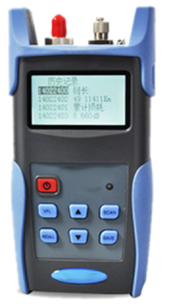
- Front panel: LCD display, ON indicators, REMOTE LED indicators, keypad.
- Back panel: Two Disassembly-proof Label, Serial Number Label, Back Cover (Battery is shown when disassembling).
- Upper end: IN and OUT Optical Port
- Optical port: FC/SC/ST interchangeable optical adapter interface Optical fiber type: Single mode Inner optical port: PC mode
- Left side: Mini USB port
- Right side: 8.4 V input jack of charger
Appearance of the Instrument

Functional Keypad
The instrument has 9 functional keys on the keyboard, including Setting Key, Back Key, OK Key, Power Key, Backlight Key, Up/ATT+ Key, Down/ATT- Key, Left/Step Key and Right/λ Key, etc. The arrangement of functional keys is shown as below

“Caution” The right key-stroke leads to one beep. The wrong or invalid key-stroke leads no beeps.
The functional keys are described in below table
| Key Name | Description |
| Setting | Press this key to for the “setting” menu, which includes display mode selection, parameters setting, etc. |
| Back | Press this key to return to the previous menu |
| OK | Press this key to confirm the selection or revision. |
| UP Arrow/ATT+ | In “Attenuation” menu, press this key to enhance the attenuation according to the step value;
In “Setting” menu, press this key to select the item in the upper position, or increase the value. |
| DOWN Arrow /ATT- | In “Attenuation” menu, press this key to weaken the attenuation according to the step value;
In “Setting” menu, press this key to select the item in the lower position, or decrease the value. |
| Left Arrow/ Step | In “Attenuation” menu, press this key to change the step value;
In “Setting” menu, press this key to select the item in the left position. |
| Right Arrow | In “Attenuation” menu, press this key to switch wavelength;
In “Setting” menu, press this key to select the item in the right position. |
| Backlight | Press this key to turn on/off the backlight. |
| Power | Press this key to switch on/off the meter. |
- Battery Power Indication
GAOTek Optical Attenuator has battery indication icon in the right corner of LCD.
- Power Supply This instrument can be powered by external power supply or built-in rechargeable batteries.
2.1 External Power Supply
Connect the input end of the dedicated charger to the 220V AC power supply and connect the output the DC8.4V input of the tester. In this way, the tester is powered by the external power supply through the charger.
2.2.2 Rechargeable Batteries
The instrument uses rechargeable battery, and the standard is especially defined with 1200mAh Li-ion battery with output of DC7.4V.
“Warning“: Do not use other charger to provide power supply. Please contact the vendor to get standard Li-ion rechargeable battery.
“Caution“: When the battery supplied for this instrument has been used expiring the charging life or are impaired, they should be dealt with control. If dealt with general waste processing system detained in the instrument, they will harm the instrument. The waste batteries must be recycled or disposed of properly at special recycling station or hazardous waste collection center.
2.2.3 Power Management
The instrument has the Auto Power Save Function, to avoid starting the system under unintentional operation and exhausting the battery. Under non-testing status, if there is no operation in 5 minutes, the instrument will be shut down automatically. The function can be started on the “setting” menu. The LCD backlight can be turned off by pressing the “Backlight” key, and press the key again to turn on the backlight. The auto backlight off function can be configured under “Setting” menu
“Warning“: Do not use other charger to provide power supply. Please contact the vendor to get standard Li-ion rechargeable battery.
“Caution“: When the battery supplied for this instrument has been used expiring the charging life or are impaired, they should be dealt with control. If dealt with general waste processing system detained in the instrument, they will harm the instrument. The waste batteries must be recycled or disposed of properly at special recycling station or hazardous waste collection center.
2.3 Switch On
Press “Power” to switch on the instrument, and the LCD would display the name and the version of the instrument. About one second later, one beep sounds and the switch-on process is completed. The instrument enters “Attenuation” menu.
2.4 Communication with PC
The instrument supports communication with PC via USB by TestManagerPro software and TestManagerPro can do two jobs: one is to upload the test results stored in the instrument to PC for further processing including filing, printing and analysing, and the other is to upgrade the embedded software via PC to protect your investment.
Communication steps:
- Connect the instrument with PC via USB cable.
- Switch on the instrument power.
- Run the TestManagerPro software on PC, click “Select” button to choose the testers type and click “Connect” button. After successful connection, the user can upgrade the instrument and do other operations. See TestManagerPro User’s Manual for details.
2.4.1 Upgrading the Embedded Software
Manufacturer will launch the latest version embedded software and host software TestManagerPro in the company website for the users to download. Make sure to visit the website frequently or contact your vendor to ensure you will always get the software of the latest version.
For the software upgrading method, please refer to the relevant part of “Communication with PC” and follow instructions of the TestManagerPro.
2.5 Safety precautions
The following general safety precautions must be observed during all phases of operation, service, and repair of this instrument. Failure to comply with these precautions or with specific warnings elsewhere in this manual violates safety standards of design, manufacture, and intended use of the instrument. The manufacturing company assumes no liability for the customers’ failure to comply with these requirements
“Warning“: Do not operate damaged equipment: Whatever it is possible that the safety protection features built into this product have been impaired, either through physical damage, excessive moisture, or any other reason, remove power and do not use the product until safe operation can be verified by service-trained personnel. If necessary, return the product to your vendor and service office for service and repair to ensure the safety features are maintained.
2.5.1 External Power Requirement
Please use the supplied Charger when operating with the instrument or charging the battery. Major parameters of the power adapter:
AC Input: 100 V ~ 240 V,50 Hz / 60 Hz, 0.35A;
DC Output: 8.4 V,1.2 A and 1500 mA (max);
“Warning“: Do not use other Charger to provide power supply. Ensuring the line supply is within the specified range. The supplied standard Charger should be used indoor only.

2.5.2 Operation Requirements
All the optical ports are located at the top of the instrument. The instrument contains components sensitive to electrostatic discharge. To prevent component damage, carefully follow the handling precautions presented below.
The smallest static voltage most people can feel is about 3500 volts. It takes less than one tenth of 1 second (at about 300 volts) to destroy or severely damage static sensitive circuits. Often, static damage does not immediately cause a malfunction but significantly reduce the component’s life. Adhering to the following precautions will reduce the risk of static discharge damage.
- Before handling the instrument, select a work area where potential static sources are minimized. Avoid working in carpeted areas and non-conductive chairs. Keep body-movement to a minimum. We recommend that you use a controlled static workstation.
- Handling the instrument by its cover. Avoid touching any components or edge connectors.
“Warning“: When connecting or disconnecting, ensure that you are grounded to bring you and the instrument to the same static potential. Do not connect this instrument to any test connector or any signal cable carrying a hazardous voltage.
2.5.3 Storage and Shipment Requirements
Temperature: -4 °F ~ 158 °F ( -20 ℃~+70 ℃ )
Altitude: up to 50,000 ft (15,200 m)
3.Navigating the Displays:
3.1 Menu Overview
The main menu of Intelligent Optical Attenuator is composed of “Attenuation” menu and “Setting” menu.
“Attenuation” Menu: “Attenuation” displays the information of wavelength, step and attenuate value, etc, which can be changed by special functional key.
“Setting” Menu: Press “Setting” button to go to “Setting” menu, which mainly configure the relative parameters. Through the “Up” and “Down” key, users can switch between different options, press “OK” to confirm the selection, after modification, press “OK” to save.
3.2 “Attenuation” Menu
Switch on the Intelligent Optical Attenuator, enter into the “Attenuation” menu as shown below

In “Attenuation” menu, press the “Step” button to switch the step, press “λ” to switch wavelength, press “ATT+” /”ATT-” to increase or decrease attenuate value.
3.3 “Setting” Menu
In “Setting” menu users can complete the configuration of relevant parameters.
There are five options including “REF”, “Rel/Abs”, “Language”, “Power Off” and “Backlight”. Press the “Up”, “Down” key to switch among different options, click “OK” to confirm the selection and then we can modify the parameters through “Up” or “Down” key, or click “Back” key to exit.
REF: Used to set the reference value to the absolute value
Rel/Abs: Switch display mode between absolute and relative value
Power Off: Click to select auto power off under non-operation of 5 minutes
Backlight: There are three options to set the auto backlight off time, including 5/10/30 minutes.
- Working with TestManagerPro
4.1 Software Functions
TestManagerPro communicates with series instruments via the serial port in PC. It can support uploading the stored data from the instrument, viewing and printing the stored results. You can easily check, manage and analyse every test result on your PC. Another very important function of TestManagerPro is that you can on-line upgrade the embedded software in the instrument with this PC software.
Basic functions of TestManagerPro:
- Basic functions of TestManagerPro include:
- Select the type of the instrument Connect the instrument
- Upload the test records stored in the instrument
- View the stored records
- Analyse the stored records
- Clear the records uploaded
- Print out the test records in the report format
- Upgrade the embedded software
- Help
4.2 System Configuration and Running Environment
4.2.1 Firmware Basic configurations required:
- PC: 586/133 MHz or above
- Memory :above 16 MB
- HD space:above 50 MB
- CD-ROM drive for installation
- Standard mouse and keyboard
- USB port
- Printer
4.2.2 Software Configuration Required
- Operating System: Windows98/ME/2000/XP/NT
4.2.3 System Configuration Recommendation
- System display mode: 800 x 600 Pixels
- Install the printer or plotter before setup
4.3 Install and Uninstall the Software on the PC
4.3.1 Install Process
- Open the package and take out the CD disk with the mark “TestManagerPro”
- Start the computer operating system.
- Insert the CD into the CD-ROM drive;
- View the contents of the CD from “My Computer”;
- Double click “Setup.exe”;
- Complete the installation according the setup wizard;
- After completing installation of the software, one short-cut icon “TestManagerPro” will be placed on the desktop automatically;
- Double-click the icon “TestManagerPro” to run the program.
4.3.2 Uninstall Process
- From the “Start” Menu, choose “Setting”;
- Open “Control Panel”;
- Click “Add/Remove Programs”;
- Select “TestManagerPro” in the list;
- Click “Change/Remove” button to remove the software automatically.
4.4 How to Use TestManagerPro
4.4.1 Connect Instrument
Make sure the instrument is well connected to the PC and configure correct settings.
4.4.2 TestManagerPro Software Operation
Graphic windows help you operate TestManagerPro software simply and easily.
- Troubleshooting
5.1 The instrument cannot be powered on.
When “Low Battery” alarms, the instrument will be shut down soon automatically. When the voltage of battery drops to a low level, the power circuit of the instrument will be locked and cannot be opened until:
- Plug the Charger into an appropriate AC wall outlet and power the instrument with external power supply.
- When the battery is fully charged, unplug the Charger and press “Power” key to switch on the instrument. And the instrument will work normally
- After the charging is completed, the charge indicator LED would be off. Remove the AC Power Adapter, and then plug it to the instrument again, the charge indicator led would be on.
This is normal. The performance of the instrument would a little reduce the battery voltage. And it would automatically charge when the AC Power Adapter is plug in, but charging would auto end in a short time due to full charged.
The instrument shuts off.
- Check the voltage of battery is low.
- Check “Auto Power Off” in “Setting” menu is set to ON or not.
Duration of battery is getting shorter
- The usage life time of new rechargeable battery is about 800~1000 cycles of charge and discharge. When you find the working duration is reduced in evidence, you should contact the vendor and replace the rechargeable batteries.
- Attenuate value error out of range
- The connector is not clean, please wipe it with special swabs dipped into a little absolute alcohol.
- The fiber is not correctly connected, please re-connect it.
- Ambient temperature changes will cause error of small signal measurement.
“Warning“: If you find that the instrument is working abnormally, please contact our vendor as soon as possible. Do not open the instrument by yourself. If the fragile parts around the instrument are damaged or have been removed, you will lose the required years of free maintenance service
- Maintenance
- The instrument should avoid mechanical vibrations, collisions, falls and other mechanical damage.
- Before the test, make sure that the optical fiber connector is clean. When cleaning the connector, don’t connect it to the tester until it is dry.
- Optical input port is precision device, it should be covered with a dust cap once it is not at work, beware of erosion from dust or other harmful gases causes measurement error.
- Periodically clean the optical connector adapter. Please use the special cotton swab to gently wipe along the circumferential direction.
- The instrument’s optical interface is FC/SC/ST interchangeable optical connector. Please use the standard adapter connector instead of others.
- Please try to stick with an adapter, be careful when plug the adapter connector to avoid scratches, and do not insert the connector to the face with polished surface, to prevent damage to the sensor.
Ordering Information
| Item | Quantity | Item | Quantity |
| GAOtek Optical Attenuator | 1 | Waterproof Package | 1 |
| Charger | 1 | TestManagerPro Setup CD (User’s Manual included) | 1 |
| Universal Adapter | 2 | User Guide | 1 |
| Master Slave USB Cable | 1 | Quality Certificate Card | 1 |
| Li-ion Rechargeable Battery (Build-in) | 1 | Maintenance Card | 1 |
| Cleaning Cotton Sticks | 1 | Packing List | 1 |