
Description
Overview
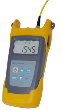
GAOTek Optical Fiber Ranger with VFL (Up to 8 Faults) is used in the test and maintenance of fiber network and comes with a built-in visual fault locator function which can detect up to 8 faults. It is a newly designed fiber optic tester and aims at fiber network installation, engineering acceptance and maintenance. It is the most lightweight, economical optical fiber barrier equipment, using OTDR principle, integrated powerful analysis software and can quickly and accurately detect the location and type of fiber optic cable failure point. Fiber test data up to 2,500 records can be stored and the screen can directly display the results.
Key Features
- Integrated visual fault location function
- Tests the length of the fiber, distance between two nodes of the fiber and determines the location of the fault point
- Maximum detection distance of 37.28 mi (60 km)
- One-touch fiber link fault location, detection and measurement
- Automatic reflection event, attenuation event analysis
- Automatic Pulse Width Control design to ensure a convenient operation.
- Provides up to 2000 test record queries
- Up to 2500 measurement results can be stored in the unit
- Storage view function through the host computer for data viewing, storage and deletion
- Display of curves and traces through software
- Auto power-off time is 10 minutes
Technical Specifications
| Maximum Measuring Distance | 37.28 mi (60 kms) |
| Wavelength | 1550 nm ±20 |
| Fiber Type | 9/125 μm single mode fiber |
| Connector Converter | FC / PC |
| Type of Detector | InGaAs APD |
| Pulse Width | Auto-adjust |
| Reflection Event Blind | ≤ 49.2 ft (15 m) |
| Range accuracy | ± 9.84 ft (3 m) + 2 x 10⁻⁴ x distance |
| Battery Type | 3 AA batteries |
| Battery Operating Time | > 2500 |
| Auto Power-off Time | 10 mins |
| VFL Output Power | > 1 mW |
| Data Storage Capacity | 2000 |
| Operating Temperature | 23 °F to 104 °F (-5 °C to 40 °C) |
| Storage Temperature | 14 °F to 158 °F (-10 °C to 70 °C) |
| Dimensions | 6.88 in x 3.54 in x 1.75 in (175 mm x 90 mm x 44.5 mm) |
| Weight | 0.612 lbs (278 g) |
Additional Information
Panel and Function
Appearance
Keypad Functions
- Short press
 to Power ON the unit. Long press (over 3 s) this key to activate or deactivate and 10 minutes for AUTO-off. The unit will automatically power off after 10 minutes of idle time.
 - Under the test mode, press this key
 to enter OTDR mode. The fiber will be tested and the results displayed on the screen.
 - Press this key
 to activate the VFL module. (User can only operate those functions of VFL such as turn ON/OFF, 1 Hz switch on the main interface and event scanning interface).
 - Use this key
 to check saved data and choose one data. Long press (over 2 s) the key to read all information of the data and press the key to delete the data.
 - Under test mode, when there are multiple measurements, user can press this key
 to review the previous measurement.
 - Under test mode, when there are multiple measurements, user can press this key
 to review the next measurement.
 - Press the key
 to save the current test data.
Operation
Power ON the instrument
Self-Test Interface
| V XX.XX: The unit version number.
Press to power on the unit then switch languages The following functions are available before the unit leaves the factory. File is to save data and test data. V-APD is to test optical device. RAM is to test data progressing unit. |
Main Interface
| After power on the unit, main interface displays the operating method and function of keypad. |
Testing Interface
| The unit starts to test 5 s later, longer time to enter test system effects battery working life. The unit will turn off test system automatically after 30 s of idle time and the next test needs 5 s to start. |
Test Result Interface
|
|
The whole fiber link length is displayed and press The first column gives the Event No. The second column gives the Event type The third column gives the Event distance The fourth column gives the Event loss (The result cannot be counted or no need to be counted.) |
Historical Record
| Historical record: The components of the record is Date and S/N. There are only 100 pcs of records every day as the limit of the length (changing the date can be saved continuously of the record) |
Modifying the Refractive Index
| Special function: In the main menu interface, please press (for over 2 s) Press Press “RECALL” key to recover the original index. |
System Time Adjustment
| Special function: In the main menu interface, please press (over 2 s) “VFL+ Press Press Save to save the data. |
Format Storage
In the historical record interface, please press SCAN+SAVE at the same time around 2 s,the system starts to format and all of the data is deleted from the storage (except time and refractive index). There will be a window to remind about the success after the process is finished.
Notes
- The max test distance 37.28 mi (60 km) means that the instrument can detect the reflection events where loss is >1 dB in 37.28 mi (60 km) of dynamic range; the detection distance of non-reflection event is 24.85 mi (40 km) (>1 dB).
- Distance accuracy depends on the length of measured distance length, if measured distance is 18.64 mi (30 km), the accuracy is ± 9.84 F (3 m) + 2 x 10-4 x 30 x 10 – 3= ± 9 m.
- Reflection Event Dead Zone refers to the minimum dead zone of reflection events under the minimum pulse width.
- Auto power-off time is 10 minutes. If the instrument is turned on and no operation in 10 minutes, the unit will turn off automatically. If no operation for 30 seconds, the back light will turn off, user needs to press any key and back light will come on again.
- The instrument can save up to 2000 measurement results in the unit; The data that is saved in the unit is showed by the mode of Date and No. User will know the test time clearly when they check the data.
- The bare unit weight without battery may vary slightly, according to customer’s requirement of different customized wavelength.
Maintenance
- Keep the fiber output ports clean, and clean them regularly with the pure alcohol cotton swabs.
- Keep the dust-proof cap clean and cover it after the test. Keep the USB port and connector clean at the same time.
- Turn off the unit and keep the output ports inactive when cleaning. Otherwise, it will lead to dangerous radiation damage.
- Use a standard optical adapter to connect with output port, otherwise, the sensor port can be damaged and the whole system performance will be affected.
- Take out the batteries when not in use for a long time.
Precautions
- There are lasers and sensors inside the unit. Please do not point the optical sources to the sensors directly, otherwise the sensor will be damaged
- Do not expose the unit to the sun directly.
- Do not look at the output ports directly when it is turned on.
- Before “scanning”, ensure the tested fiber is well connected to the “OTDR port” or “VFL port”. Do not plug in/out the fiber during the test.
Applications of the Instrument
- Fiber Optic CATV Engineering
- Optical fiber communication engineering
- Research on Optical Fiber Sensing
- Production and research of optical devices
- Other fiber engineering
Standard Package
- Fiber ranger – 1
- User Manual – 1
- USB – 1
- Cleaning Swab – 1
- Battery – 3
- CD – 1
- Certification – 1