
Description
Overview
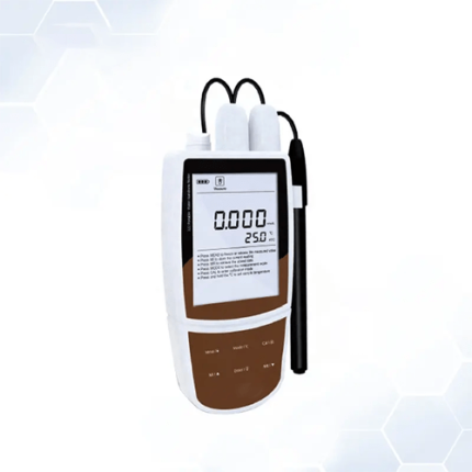
The GAOTek Optical Power Meter with Wavelength Detection is a handheld device used to measure power of optical devices featuring automatic wavelength identification, automatic wavelength switching, and inbuilt data storage with a capacity of 1000 tests. Combined usage with a handheld optical light source offers a quick and accurate testing solution on both single-mode and multi-mode fibers. This newly designed optical power meter aims at fiber network installation, engineering acceptance, and maintenance of fiber networks.
Key Features
- Automatic wavelength identification and switching
- Data storage function, up to 1000 test records
- Automatic frequency identification and tone detection
- Intelligent backlight control (light intensity can be adjusted properly according to ambient light, which greatly reduces power consumption)
- Reference power level can be set up and stored
- User self-calibration function
- Auto-off function can be activated or deactivated
- AA alkaline and AC adapter for power supply
- USB communication port for downloading saved testing records
- Up-to 200 hours battery life
- Low battery indication.
Technical Specifications
| GAO-OPM-105– A | GAO-OPM-105– B | ||
| Calibration Wavelength | 850 nm, 1300 nm, 1310 nm, 1490 nm, 1550 nm, 1625 nm | ||
| Detector Type | InGaAs | ||
| Measurement Range | -70 dBm to 6 dBm | -50 dBm to 26 dBm | |
| Uncertainty | ±0.15 dB (3.5 %) | ||
| Linearity | ±0.02 dB | ||
| Display Resolution | 0.01 dB | ||
| Frequency ID | 270 Hz, 330 Hz, 1 KHz, 2 KHz | ||
| Wave ID | 1310 nm, 1490 nm, 1550 nm, 1625 nm | ||
| Date Storage Capacity | 1000 | ||
| Communication Port | USB (B type) | ||
| Optical Connector Type | FC, SC, ST interchangeable | ||
| Alkaline Battery | 3 x AA, 1.5 V | ||
| Power Supply Adaptor | 8.4 V | ||
| Battery Time | 200 h | ||
| Operation Temperature | 14 °F to 140 °F (-10 ℃ to 60 ℃) | ||
| Storage Temperature | -13 °F to 158 °F (-25 ℃ to 70 ℃) | ||
| Dimension (L x W x H) | 7.08 in x 3.54 in x 1.77 in (180 mm x 90 mm x 45 mm) | ||
| Weight | 0.55 lb (250 g) | ||
Additional Information
Panel Description
Front

 Power Key
This key is used to turn the instrument ON/OFF.
Power Saving setting: the unit will automatically shut off after 15 minutes idle time, no matter whatever is the condition of battery power supply or AC power supply. Once this setting is chosen, the “auto-off” will display at the bottom left of the screen. This power saving is the default setting and when the power meter is opened, it will enter into this mode. Short pressing the power key will turn off the auto power saving mode.

![]() Wavelength Selection/Wavelength Identification
Wavelength Selection/Wavelength Identification
Short press this key to switch the wavelength and display it on the top left of the LCD screen, 1310 nm is the default wavelength.

Press the ![]() for 2 seconds to enter into the wavelength auto-identification mode and on the upper right of screen “AU” is displayed. Long press this key to quit this function.
for 2 seconds to enter into the wavelength auto-identification mode and on the upper right of screen “AU” is displayed. Long press this key to quit this function.

![]() Backlight control
Backlight control
There are two modes of backlight control, press this key to choose one mode.
“LDR” is the intelligent backlight control mode. Power meter will turn off/on the rear side in about 15 seconds based on the outside light condition and this is the default mode.
Back light control key mode: Press ![]() to turn on/off the back light.
to turn on/off the back light.
![]() Saving/Data-view Key
Saving/Data-view Key
This instrument can saving not less than 1000 data. Press![]() , the screen will display the data saving No. then double press the
, the screen will display the data saving No. then double press the ![]() key to confirm the saving.
key to confirm the saving.

Data view key: Long press the ![]() key to enter into the data view interface, short press the
key to enter into the data view interface, short press the ![]() key to view the data.
key to view the data.

![]() Delete/Cancel Key
Delete/Cancel Key
- Data Delete: When viewing the data, press
 to delete the record.
 - Cancel the saving: When in the saving mode, press to cancel the current data saving.
![]() Unit switch key
Unit switch key
Press this key to switch between the absolute measurement (dBm) and relative measurement (dB) and xW of the optical power.
mW, dBm conversion:10 log(mW)=(dBm)
mW, uW, nW conversion:1 mW=103 uW=106 nW

![]() REF Setting
REF Setting
To store the current power value as the reference value which will be displayed on the top right of the LCD screen, at the same time the “Ref” also display on the right top. It will compare the current power with the reference power and show the relative power value in dB.
The relationship between relative value (dB), absolute value (dBm), and Ref value: relative value=︱absolute value︱ -︱Ref︱

“B/L SET” Backlight Indicator
Indicate backlight control mode. Green light indicates “LDR” intelligent backlight control mode, Red light indicates key-control mode.

“LDR” Intelligent backlight controller
In the intelligent backlight control mode, the controller will automatically adjust the backlight with the outside light, which helps to save the power.
Screen
Displays the data and the instrument working mode.
Sides

Power Supply unit port
The instrument can connect with the AC adaptor.

![]() Note: Please use only the power supply unit supplied with the tester, using other kinds of PSU may cause damage for the instruments.
Note: Please use only the power supply unit supplied with the tester, using other kinds of PSU may cause damage for the instruments.
USB Port
Use the USB cable supplied, to connect the Optical Power Meter to The USB port on the PC.

Dust Cap
In order to protect the optical connector and avoid damage to the connector, when not in use make sure that you place the dust cap over the connector.
Optical Connector
The standard of this power meter connector is PC & Φ2.5 mm universal connector. Screw off the FC connector, it will turn to &Φ 2.5 mm universal connector.

![]() Note: When changing the optical connector, take care of the connector and the end-face. FC connector can connect with FC adaptor, Φ2.5 mm universal connector can connect with FC, SC, ST adaptor.
Note: When changing the optical connector, take care of the connector and the end-face. FC connector can connect with FC adaptor, Φ2.5 mm universal connector can connect with FC, SC, ST adaptor.

![]() Note: The dust on the connector will affect the accurate measurement value, so please clean the connector and the patch cord end-face before doing the test.
Note: The dust on the connector will affect the accurate measurement value, so please clean the connector and the patch cord end-face before doing the test.
Use alcohol and the cotton swab to clean the connector. Dip the cotton swab with alcohol, insert the cotton swab in the connector, slightly rotating the cotton swab. After that change the dry cotton swab and clean it again.

Label
Label content includes the function and the instrument information.
Bracket
Collapsible metal bracket, can be adjusted to 0 degree – 90 degree.
Battery Pack
3 1.5 AA batteries can be inserted.
![]() Note: When inserting the batteries, take a note of their positive (+) and negative (-) connector orientation. The negative battery connector should be against the spring. And do recycle the battery, do not throw the battery into the dustbin, that will be dangerous.
Note: When inserting the batteries, take a note of their positive (+) and negative (-) connector orientation. The negative battery connector should be against the spring. And do recycle the battery, do not throw the battery into the dustbin, that will be dangerous.
Software
Installing the device
- Run the software in the PC.
- Double click that, “exe” program, will pop up.
- Click “INSTALL” and after seconds, pop up shows
- Press “OK”, exit this install interface.
- Use USB cable connect with power meter and the PC, switch on the instrument, pop up will display
- Press “NEXT”, Pop up displays
Wait for a second.

Press Finish, complete the driver installation.
After successfully installing the devices, switch off the power meter and disconnect the USB.
Installing the application software
Run the CD in the PC, find the “setup” file.

Double click this icon. Press “Next”, Pop up displays. Choose “I accept ……”, Click “Next”, pop up displays. Wait for a second, next pop up displays
Click “Finish” to complete the installation.
Software Function Instruction
The software has two functions: data processing and instrument setting
After installing the software, find the short cut icon for this software.

Double click this icon, open the software, pop up the software interface, data processing is the default interface once open the software.
Data Processing

Data Processing interface includes 4 parts.
Manual:
- Port Option: Drop down the manual, choose the right port, which is the same port that connects the PC with the power meter.

2. Connect icon: Makes the PC connect with the power meter, and communicate.
![]()
3. Language option: Drop-down the manual, Find the right language which the user prefers.
- Function interface option: Two functions for option – data processing and the instrument setting, drop-down the manual to choose.

5.Save button: save the current measurement data as the EXCEL file, convenient for the user to view and analysze the data on the PC.
![]()
6.Exit button: disconnect the communication, close the software.
![]()
Testing information form
Fill the information in the blanks

Printing button to print the measurement value
Data process button
- Upload the data to the PC, display the data on PC, for the user view.
![]()
2. Delete the choosen data.
![]()
3.Delete all the data that is saved in the instrument.
![]()
4.Data display area
To display the saved data of the instrument
Power Meter setting

Power Meter setting interface, which includes 4 parts:
- Menu bar (Please refer to the description in the data process interface)
- Calibration: The user can do the self-calibration.
![]()
3.Time Setting

4.Recover the factory default setting: Power meter calibration recovers the factory default setting.
Operation Instructions
1. Powering the Optical Power Meter
The optical power meter can be either battery powered or AC adaptor powered, giving total flexibility for most testing sites and situations
- AA battery: When using AA battery,
 will display on the left top of the screen.

Power Grade:

Fit the battery,

Press the clip fastener on the battery compartment cover down. Remove the battery compartment cover, remove all three batteries making a note of their positive and negative connector orientation. The negative battery connector should be against the spring. Insert 3 new 1.5 VV AA battery. Refit the battery compartment cover. The clip fastener should click shut.
![]() Note: Make sure that you insert the batteries with their positive and negative connectors correctly aligned.
Note: Make sure that you insert the batteries with their positive and negative connectors correctly aligned.
- Power Supply Unit
When the battery is used out, the power supply unit can be used and at this time on the left top of the screen, there will be a![]() .When the battery is in the power meter, and there is still enough electricity, the tester will choose AC power supply as the priority.
.When the battery is in the power meter, and there is still enough electricity, the tester will choose AC power supply as the priority.

When using the AC adaptor, connect the power plug and insert it into the AC socket.

![]() Note: Please use only the power supply unit supplied with the tester, using other kinds of PSU may cause damage for the instruments.
Note: Please use only the power supply unit supplied with the tester, using other kinds of PSU may cause damage for the instruments.
2. Power On the optical power meter
First of all insert the battery or the PSU, if there is no laser in, press![]() to open the tester, the opening interface is shown.
to open the tester, the opening interface is shown.

When the tester is in standby, pressing the![]() key can cancel or choose auto-off function. If auto-off function is chosen, the “Auto-off” will display on the left bottom of the screen.
key can cancel or choose auto-off function. If auto-off function is chosen, the “Auto-off” will display on the left bottom of the screen.
3. Backlight setting
After opening the optical power meter, long press ![]() and choose backlight control mode.
and choose backlight control mode.
- “LDR” Intelligent backlight control mode
Long press![]() ,“B/L SET” is green (6-6), after 10 seconds, the green indicator goes off and the LDR controller will automatically adjust the backlight within 15 seconds with the outside light, which saves the power.
,“B/L SET” is green (6-6), after 10 seconds, the green indicator goes off and the LDR controller will automatically adjust the backlight within 15 seconds with the outside light, which saves the power.

- Choose the key control backlight mode.
Long press![]() , “B/L SET” indicator turns to red (6-7), enters into key control backlight mode. After 10 seconds the indicator goes off, short press
, “B/L SET” indicator turns to red (6-7), enters into key control backlight mode. After 10 seconds the indicator goes off, short press![]() can turn ON/OFF the backlight.
can turn ON/OFF the backlight.

4. Output power measurement
- Take off the dust cap, connect with the patch cord.
![]() Note: Make sure the connector and the end-face of the patch cord is clean, and take note on the type of the patch cord, make sure the correct patch cord are connected.
Note: Make sure the connector and the end-face of the patch cord is clean, and take note on the type of the patch cord, make sure the correct patch cord are connected.
- Select the wavelength
Short press ![]() , select the calibrated wavelength, notice if the selected wavelength is not the same with the laser source wavelength, that will cause the error of the measurement value. There are 6 calibration wavelengths for selection.
, select the calibrated wavelength, notice if the selected wavelength is not the same with the laser source wavelength, that will cause the error of the measurement value. There are 6 calibration wavelengths for selection.

- Unit switch
Press ![]() to switch between the absolute measurement (dBm) and relative measurement (dB) and xW of the optical power.
to switch between the absolute measurement (dBm) and relative measurement (dB) and xW of the optical power.

- Relative value measurement
Each wavelength can set the Ref value, Press![]() ,set the current value as the ref value, and automatically calculate out the relative value. (Right top of the screen will display the “ref” and setting dBm value 6-10)
,set the current value as the ref value, and automatically calculate out the relative value. (Right top of the screen will display the “ref” and setting dBm value 6-10)

- Data processing
Data saving and deleting: The power meter has 1000 data saving memory. When the output power measurement, press![]() , at the right top of the screen will display the data saving No. eg: “0008” as per the image below.
, at the right top of the screen will display the data saving No. eg: “0008” as per the image below.
Hint: If the data save or not, double press ![]() confirm the saving,
confirm the saving, ![]() cancel saving.
cancel saving.

Data view & delete: Long press![]() , can view the saving record, the screen will display the last saving data. Short press
, can view the saving record, the screen will display the last saving data. Short press![]() , can view the data from the last record. Press
, can view the data from the last record. Press![]() to delete the record, long press
to delete the record, long press ![]() exit the data view.
exit the data view.

5. Data Communication
![]() Note: Before proceeding for the data communication, make sure the driver and application software are installed successfully
Note: Before proceeding for the data communication, make sure the driver and application software are installed successfully
Open the software
Double click to open the software, user can choose the language on request
Connect Optical power meter with computer via USB cable and turn on the power meter.
From the Device Manager: “Port (COM<P), We can see that power meter port is “COM4”.

Therefore, choose “COM4”port shown as below in the figure.

Next click “Connect” as shown in below figure, a pop up will show a successful connection window, click “OK” to finish the connection, the unit can be communicated with computer properly.

Data edit
Firstly, input the following basic information as shown in the figure below.

Then click “Upload data”, the saved data in the unit will be uploaded onto computer and shown as per the figure below.

Data edit at data display area, including data delete, data save and data printing.
Select the required data, click “delete one” to delete it from the sheet, as shown in the figure below. In addition, the corresponding data from the power meter also will be cleared accordingly.

Click “Delete all”, a pop up window will appear as shown in figure below, click “OK” to delete all data, also will clear all saved data from the unit.

Click “Save” a pop up window as shown in the figure below will appear, input the file name, choose the save path and press “ok” for storage.
Click ![]() on the software, you can print testing report directly, you can also print the testing report from Excel.
on the software, you can print testing report directly, you can also print the testing report from Excel.
Function setting on the unit
Under function setting mode to switch the interface as shown in the figures below:

There are other items which can be set on the unit:
- Optical Power Calibration
![]()
Input the corresponding optical power and click “calibration”, users can recalibrate the optical power by themselves.
- Time setting

Input the corresponding date and time, and then click “Set” to modify the time and date accordingly.
- Back to factory mode
![]()
Click “Reset”, the unit will revert back to the default setting (factory mode setting).
- Close software
Click exit,a pop up window will appear as shown below:

Wavelength Automatic Identification
Connect power meter with its same serial light source.
Enable light source to be under “Wave ID” operation mode: press ![]() of light source to emerge light output from light source. Hold down
of light source to emerge light output from light source. Hold down![]() for a few seconds. Light source will enter into Wave ID mode, also “–AU” will be shown on the upper right of LCD.
for a few seconds. Light source will enter into Wave ID mode, also “–AU” will be shown on the upper right of LCD.
Enable power meter to be under “Wave ID” operation mode: Hold down ![]() for few seconds,power meter will be enter into Wave ID mode, also “–AU” will be shown on the upper right of LCD.
for few seconds,power meter will be enter into Wave ID mode, also “–AU” will be shown on the upper right of LCD.
Once the ID information is changed from light source (press![]() to change wavelength), after 3 to 5 seconds later, the detected information on optical power meter also will be changed automatically according to light source. Please refer to below figure for easy understanding.
to change wavelength), after 3 to 5 seconds later, the detected information on optical power meter also will be changed automatically according to light source. Please refer to below figure for easy understanding.
Exit Wave ID mode: Hold down![]() again to exit Wave ID mode from power meter and hold down
again to exit Wave ID mode from power meter and hold down ![]() again to exit Wave ID mode from light source.
again to exit Wave ID mode from light source.
 Frequency detection
![]() When using tone detection function, following requirements have to be taken into account:
When using tone detection function, following requirements have to be taken into account:
For A: Tone detection will be effective only with measurement range between +6 dBm -40 dBm.
For C: Tone detection can be worked only with measurement range between +26 dB – 20 dB, because the detected frequency will be unstable when the power is weak.
To act tone detection on Power Meter:
- Connect power meter with its same serials light source.
- Output frequency from MATCHED optical light source: Press
 to emerge light from the unit, press
  for a very short second,MATCHED light source will output frequencies of 270 Hz,330 Hz,1 KHz,2 KHz accordingly,which will be shown on the upper right of the LCD in MATCHED light source. In the meantime, the power meter will detect the corresponding frequency automatically from MATCHED light source. Please refer to below figure for better understanding:

![]() Note: Frequency ID and wave ID cannot be operated at the same time.
Note: Frequency ID and wave ID cannot be operated at the same time.
To avoid risk of serious eye damage, please do not look into the optical port of laser source at any time.
Power off
- Automatic power off: When auto-off function is activated, the unit will turn itself off automatically after 10 minutes idle time, whatever the power supply is with alkaline batteries or is with power supply adaptor directly.
- Manual power off: Under any operation mode, hold down for a few seconds to turn the unit off.
Note: With either power off operation, the unit will store the last calibration wavelength and backlight control mode automatically, which will be the default setting when user turns unit on next time.
Troubleshooting
| Problems | Possible cause | Solution |
| Faint display on the LCD screen | 1. Power is off
2. The battery power is too low |
1. Press 2. Change the batteries |
| Inaccurate measurements | 1. Optical connector is not clean.
2. incorrect fiber connection |
1. Clean optical connectors
2. Re-connect the fiber |
General Maintenance
Always keep the connector ports of your power meter clean.
Do not use bad quality optical fiber connectors/adaptors, otherwise, it will damage the interface of detector that will greatly affect the performance of the unit.
Try to use only the adaptor supplied.
Once not in use, make sure dust-proof cap is placed properly over the optical ports.
Carefully plug in/out for fiber connectors/adapters to avoid scratches on the port of the power meter.
Keep regular cleanings on optical port of power meter, please clean with cotton swabs supplied using alcohol properly.
Standard configuration
| No. | Name | Qty |
| 1 | Optical Power Meter | 1 |
| 2 | User Manual | 1 |
| 3 | USB cable | 1 |
| 4 | CD | 1 |
| 5 | 1.5 V AA battery | 3 |
| 6 | Power Supply Unit | 1 |
| 7 | Cotton Swabs | 1 |
| 8 | Carry Bag | 1 |