Description
Overview
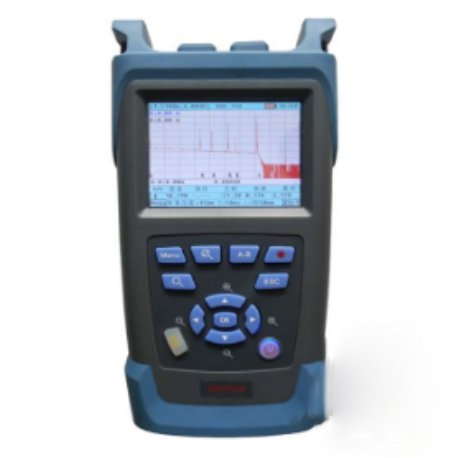
The GAOTek OTDR with VFL Tester is designed for user-friendliness and portability. It is equipped with a 3.5 inches (88.9 mm) color LCD and a touch screen. This instrument is mainly used in applications such as fiber testing and troubleshooting. It is also used in optical fiber cable attenuation. It provides the loss distribution curve of the optical fiber and cable as well as the loss of two points and the joint loss.
Features
- Average test mode and real-time test mode
- 3s starting time: test as soon as open the tester
- Support touch screen and easy to use
- Built-in VFL function: a perfect combination with OTDR
- Light warning function: automatically detect and protect the injection of light
- Single port, double wavelength output: switch between 1310 nm/1550 nm wavelength
- Hot key function: swift location and analyze events
- Friendly and simple operation interface with powerful intelligent test mode: no need complicated training
- Mass storage can save more than 10000 test waveforms
- Low power consumption design: 50h long battery life makes it suitable for field work
- Adopt changeable OTDR output port: it becomes more convenient to clean the end face
- Support FC/SC/ST adapters
- USB port: support to upload test results and on-line upgrading
- Adopt dust-proof, moisture-proof and shock-proof design, suitable for field work
- Auto, Manual and Real-time test three test modes
Auto Test: automatically calculate fiber length, set sampling parameters, gain curve, display event list and gained curve
Manual Test: offer and operate all the tools of a complete OTDR test; user also can control all the test parameters
Real-time Test: real-time test fiber and then compare the current result with previously gained curve; it can save time when you are going to test large number of fibers.
- A secondary analysis of test results
- Large color LCD touch screen: intuitive and easy to use
- Real-time clock function: display the current time and offer the recording time for data storage
- Lithium polymer battery
- Battery voltage monitoring display
- Energy saving design: auto power off, low voltage detection, low voltage power off
- Offer professional management software: analyze, edit, print curve via PC
Technical Specifications
| Optical output Connector | FC-PC (standard) | |
| Display Screen | 320×240, 3.5 in (88.9 mm) colored LCD (touch screen) | |
| Port | USB port | |
| Working Environment Temperature | 32 oF to 122 oF (0 ℃ to 50 ℃) | |
| Storing Environment Temperature | -4 oF to 140 oF (-20 ℃ to 60 ℃) | |
| Relative Humidity | 0% to 95% (non-condensing) | |
| Dimension (L×W×H) | 8.67 in x 4.13 in x 2.36 in (220 mm × 105 mm × 60 mm) | |
| Weight | 2.2 lb (1 kg) | |
| Duration of the Battery | Standby | >50 h |
| Testing Time | >20 h | |
| Wavelengths | 5.16 x 10⁻⁵ in/ 6.10 x 10⁻⁵ in ± 7.87 x 10⁻⁷ in (1310 nm/1550 nm ± 20 nm) | |
| Dynamic Range | 28/26 dB | 32/30 dB |
| Range | 0.621 mi, 1.24 mi, 2.49 mi, 4.97 mi, 9.32 mi, 18.6 mi, 37.3 mi, 55.9 mi, 74.6 mi
(1 km, 2 km, 4 km, 8 km, 15 km, 30 km, 60 km, 90 km, 120 km) |
0.621 mi, 1.24 mi, 2.49 mi, 4.97 mi, 9.32 mi, 18.6 mi, 37.3mi, 55.9 mi, 99.4 mi
(1 km, 2 km, 4 km, 8 km, 15 km, 30 km, 60 km, 90 km, 160 km) |
| Fiber Under Test | single mode | |
| Pulse Width | 10 ns/20 ns/50 ns/100 ns/200 ns/500 ns/1 us/2 us/5 us/10 us/20 us/Auto | |
| Working Current | 450-600 mA | |
| Power Consumption | About 4 W | |
| Event Dead Zone | ≤6.56 ft (2 m) | |
| Attenuation Dead Zone | ≤32.8 ft (10 m) | |
| The VFL Output Power | >2 mW | |
| The Capacity of Storing Waveform | >10000 | |
| Degree of Linearity | ±0.05 dB | |
| Loss Threshold | 0.01 dB | |
| Loss Resolution | 0.01 dB | |
| Sampling Resolution | 0.52 ft to 16.4 ft (0.16 m to 5 m) | |
| A Veraging Time | 5 s, 15 s, 30 s, 1 min, 2 min, 3 min | |
| Power Consumption | <3 W | |
| Alarm with Light | >1 uw(-30 dBm) | |
| Distance Uncertainty | ± (1 m+ sampling inter Val + range×0.005%) | |
| Weight | 2.20 lb (About 1 kg) | |
Additional Information
Interfaces of the tester
Side Interface
Top Interface
Panel

Usage
1. Test Fiber Link
The Procedures are as follows:
- Firstly, please make sure that the battery is installed well or the power adapter has been inserted; there is no light is injected into the fiber; press【
 】button for 3s to switch on the tester.
 - Choose the test wavelength.
- Set test mode and testing parameters.
- Clean the fiber; clean the connectors; clean fiber adapters; and check the adapter is FC/PC type.
- Connect the fiber with the OTDR output port.
- Press
 button to gain the waveform.
 - After the test is finished, the tester will list the events automatically according to the set event threshold.
The test result can be checked from the event list when the curve analysis is completed.
Caution: Before testing, please make sure there is no operating light in the optical fiber, otherwise the measurement result will be inaccurate or even result in the permanent damage of the instrument, The dimension of the fiber is very tiny, so, even a very small dirty on the fiber connector, can affect the accuracy of the test result. So, please clean the fiber connector, as well as the interface before testing.
The optical fiber connector can be cleaned with ordinary industrial alcohol and the cleaning cotton swabs (standard accessories).Stretch a cleaning cotton swab with industrial alcohol into the port of an optical fiber connector, turn it gently and repeat the operation with another clean and dry cleaning cotton swab.
2. Testing mode and parameter
- Press or touches【Menu】to enter the menu.
- Press [
 ]and【
]and【 】to move the curser to the “Parameter set”
 - Press【 OK 】button or touch to confirm to enter the interface of parameter setting
2.1 Set testing range
Usually, the corresponding predefined range in the setup of distance range is chosen in line with the actual optical fiber length to guarantee high measurement accuracy.
Please operate as follows
- Please touch or press 【
 】and【
】and【  】button, and move the curser to the “distance range”, and press 【
 】to switch to the parameter, then press 【OK】to enter to pop up a pull-down menu.
 - Touch or press 【
 】 and 【
 】to choose the item to be set, and press 【OK】to confirm the parameter to be set.
2.2 Set Pulse width
The pulse width has an impact on the dynamic range and the resolution of the measured trace. If a narrower pulse width is chosen, a higher range resolution and a smaller dead zone will be realized, but the dynamic range will have a loss; if a wider pulse width is chosen, a larger dynamic range and a longer optical fiber length will be realized, but the range resolution and the dead zone parameter will be both affected.
The “Setup of the Pulse Width” option has 10 predefined items in all:10ns, 20ns, 50ns, 100ns, 200ns, 500ns, 1000ns, 5us, 10us, 20us. The setup is valid in the manual measurement mode only. Please operate as follows:
- Press or touches [
 ] and [
  ] to switch to the “Pulse width” option and 2【
  】to switch to the parameter.
 - Press【OK】, a pull-down box menu of range will pop up after that. Touch or press 【
 】 and【
  】to choose the item to be set, and click【OK】 to confirm the item to be set.
2.3 Set Average time
The average time has a direct effect on the signal-to-noise ratio of the measured trace. A larger time corresponds to a longer measuring duration, a higher signal-to noise ratio and larger dynamic range. Thus, choose the maximum average time as much as possible when measuring a long optical fiber or viewing a remote event.
The operation methods is the same as that in 2.1
2.4 Set Laser wavelength
Choose the wavelength of OTDR, and 1310 nm and 1550 nm are optional. The factory default of laser length is 1550 nm.
The operation method is the same as that in 2.1.
2.5 Set Measuring mode
The optional modes are Average mode and Real-time mode. Under the real time mode, the OTDR can measure the connectivity of the optical fiber and update the testing curse in real time. And the testing will not stop unless you press 【 ![]() 】 or 【
】 or 【![]() 】to stop the testing; Under the Average mode, based on the average time to be set, the instrument will accumulate and average the testing data, when the testing time is longer than the predefined time, the testing stopped.
】to stop the testing; Under the Average mode, based on the average time to be set, the instrument will accumulate and average the testing data, when the testing time is longer than the predefined time, the testing stopped.
2.6 Set Index of reflection
The index of the optical fiber influences the transmission speed of the laser in the optical fiber. So an accurate index of reflection can affect all of the OTDR testing referring to distance, such as the location of event, attenuation, section length and the total length. Generally speaking, the index of reflection is provided by the manufacturer of the optical fiber. We provide a default index of reflection for each wavelength. And user can set according to their need, and please check the parameter before each testing. It can be set to be any value between 1.0 and 2.0 and correct to four decimal places. Its factory default is 1.4666.
Please operate as follows:
Touch or press 【![]() 】and【
】and【![]() 】to switch to the “Index of Reflection” option and 【
】to switch to the “Index of Reflection” option and 【 ![]() 】to switch to the parameter value, press【OK】to pop up the Edit of Index of reflection.
】to switch to the parameter value, press【OK】to pop up the Edit of Index of reflection.
Touch soft keyboard directly or press 【![]() 】,【
】,【![]() 】, 【
】, 【![]() 】, 【
】, 【![]() 】move curser to the software, press 【OK】to edit the value or “ ”to delete the value. Finally, touch “save” directly or move the curser to “save”, and then touch 【OK】 to confirm the setting.
】move curser to the software, press 【OK】to edit the value or “ ”to delete the value. Finally, touch “save” directly or move the curser to “save”, and then touch 【OK】 to confirm the setting.
2.7 Set Scattering coefficient
The Scattering coefficient is used to show the backscattering amount of specific optical fiber. And the scattering coefficient is used to calculate the event loss and reflectivity. And the scattering coefficient is provided by the manufacturer of the optical fiber. And the default is 60.50 db, and the customer can modify according to their needs.
The operation method is same as that 2.6
2.8 Non-Reflection Threshold
Setup of the non-reflection threshold has a direct bearing on the existence of the insertion loss events in the event list. The loss events equal to or larger than the threshold are listed in the event list. It is 0.20 dB by default.
The operation method is same as that in 2.6
2.9 Reflection Threshold
Setup of reflection threshold: It has a direct bearing on the existence of reflection events in the event list. Only the events with a reflection value equal to or larger than the threshold are listed in the event list. It is 60.50 dB by default.
The operation methods is same as that in 2.6
2.10 Ending Threshold
Set up the minimum value of ending event, it is used to judge the end of the optical fiber, and it is 3 dB by default.
And the operation method is same as 2.6.
2.11 Restore the defaults
Restore parameters of the OTDR to factory default.
3. File operation
3.1 Save testing result
Press or touch【Menu】to enter the menu. Touch 【Save】or press【 ![]() 】 and 【
】 and 【![]() 】to choose the items to be set, press【OK】to switch to the file save.
】to choose the items to be set, press【OK】to switch to the file save.
The file folder would be named as the current date automatically, and the user can press“ ”to delete the name of the file and modify it according to the actual need.
The operation method is same as that 2.6.
3.2 File system
File system includes Open, Saved As, Delete and Format. Enter it through the “File” submenu under “menu”.
3.2.1 Open
Open a file folder
- Firstly, enter the first-lever directory, please see the following picture.
- Touch or press【
 】and【
】and【  】to choose the file folder;
 - Press【OK】to enter the second level directory, or press 【ESC】or Cancel to exit from the file system.
Open a file
- Touch or press【
 】or【
】or【  】to choose the file to be opened
 - Press【OK】to open the file, or press【ESC】or Cancel to exit from the file system.
3.2.2 Saved As
The operation method is same as 3.1.
3.2.3 Delete
Delete a file folder
- Press【
 】and【
】and【  】to move the curse to the file folder to be deleted, press【A-B】for choosing. (It can delete multi- file folders at the same time).
 - Touch “Delete” or move curser to the “Delete”, press “OK”
Delete a file
- Touch or press【
 】and【
】and【 】to move the curse to the file to be delete, press 【A-B】for choosing. (It can delete multi files at the same time).
 - Touch “Delete” or move curser to the “Delete”, press “OK”
Standard Accessories
| Names | Quantity |
| OTDR | 1 |
| Battery Charger | 1 |
| User Manual | 1 |
| CD (including imitated analysis software) | 1 |
| USB Data Cable | 1 |
| Carrying Bag | 1 |


